
Conic tube and rolling method thereof

A bobbin and cone-shaped technology, which is applied in the field of yarn guiding to form a conical bobbin package, can solve the problems of bobbin rotation fluctuation and uncontrollability, and achieve the effects of reducing the number of bobbins, preventing entanglement, and increasing the winding length

Inactive Publication Date: 2006-08-16
SAURER GERMANY GMBH & CO KG
View PDF3 Cites 2 Cited by
  • Summary
  • Abstract
  • Description
  • Claims
  • Application Information

AI Technical Summary

Problems solved by technology

Since the circumference length of the tapered bobbin is different from the bobbin axis, the number of revolutions of the bobbin fluctuates and cannot be controlled

Method used


Image

  • Conic tube and rolling method thereof
  • Conic tube and rolling method thereof
  • Conic tube and rolling method thereof

Examples


Embodiment Construction

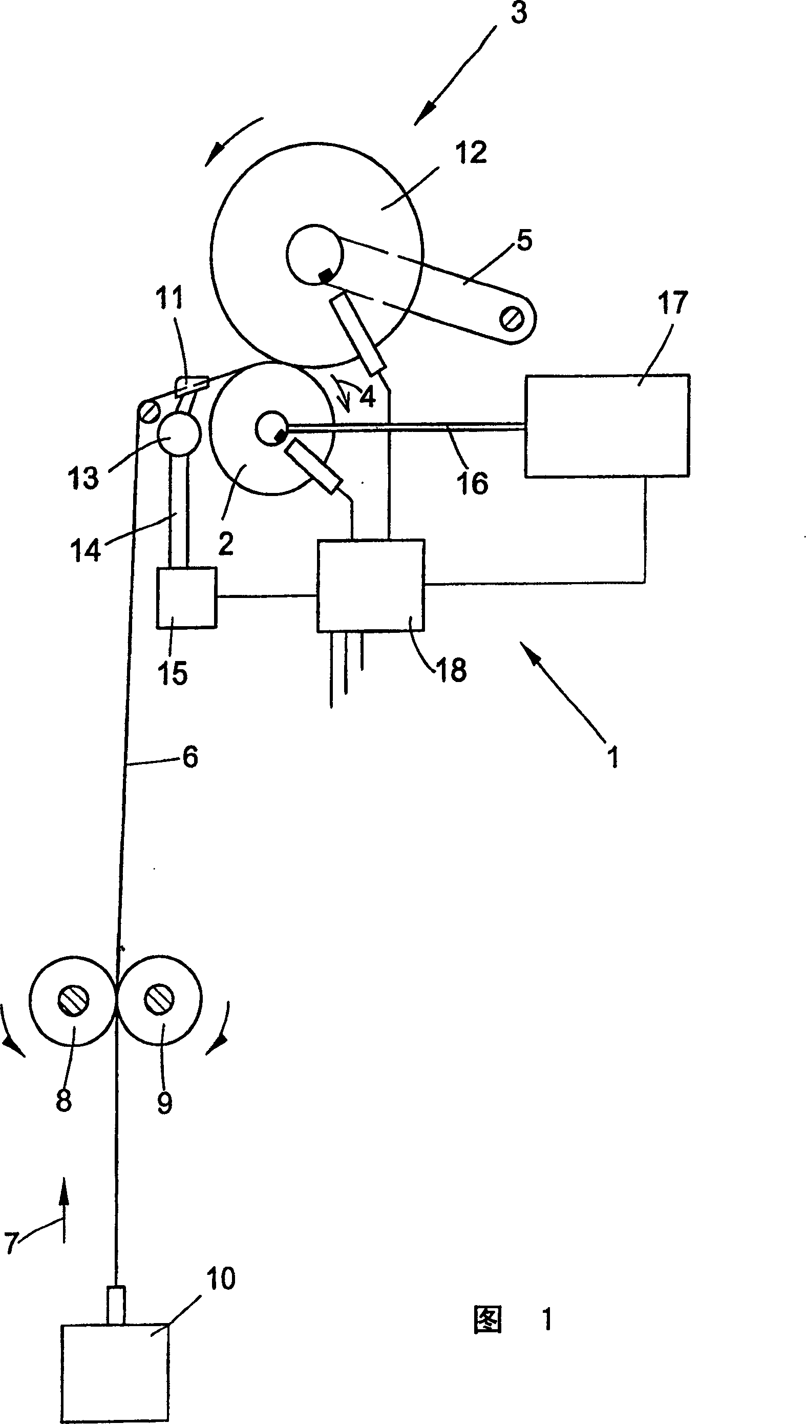
[0023] Figure 1 shows a winding device for the production of conical packages on a rotor spinning machine. The winding device 1 has a drum 2 which drives a conical bobbin 3 by means of friction. Drum 2 rotates in the direction of arrow 4. The bobbin 3 is supported by a rotatable bobbin carrier 5 and rests against the drum 2 . Roller 2 is under pressure. The yarn 6 is drawn in the direction of the arrow 7 by means of the cooperating yarn delivery roller pair 8, 9 from the winding position of the spinning box 10 at a constant yarn speed, and the yarn is wound into a bobbin by means of a reciprocating yarn guide 11 3 in a roll of 12. The yarn guide 11 is a part of the reciprocating mechanism 13, which is connected to the motor 15 through an effective connector 14, and is driven by the motor. The drum 2 is driven by the shaft of the motor 17 . Motors 15 and 17 are all controlled by a microprocessor, and the intersection angle α of the conical bobbin 3 is related to the positi...


PUM


Abstract

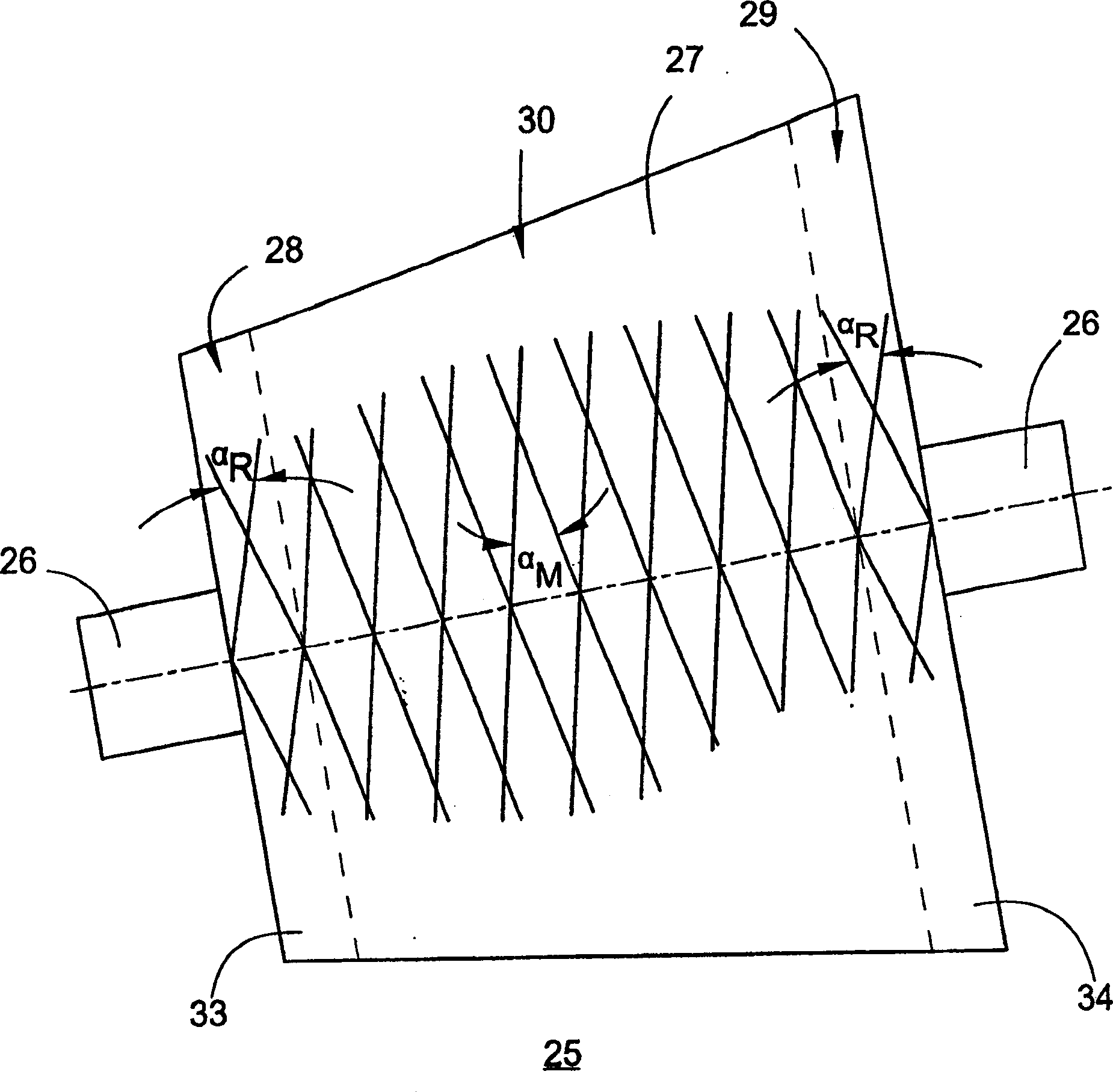
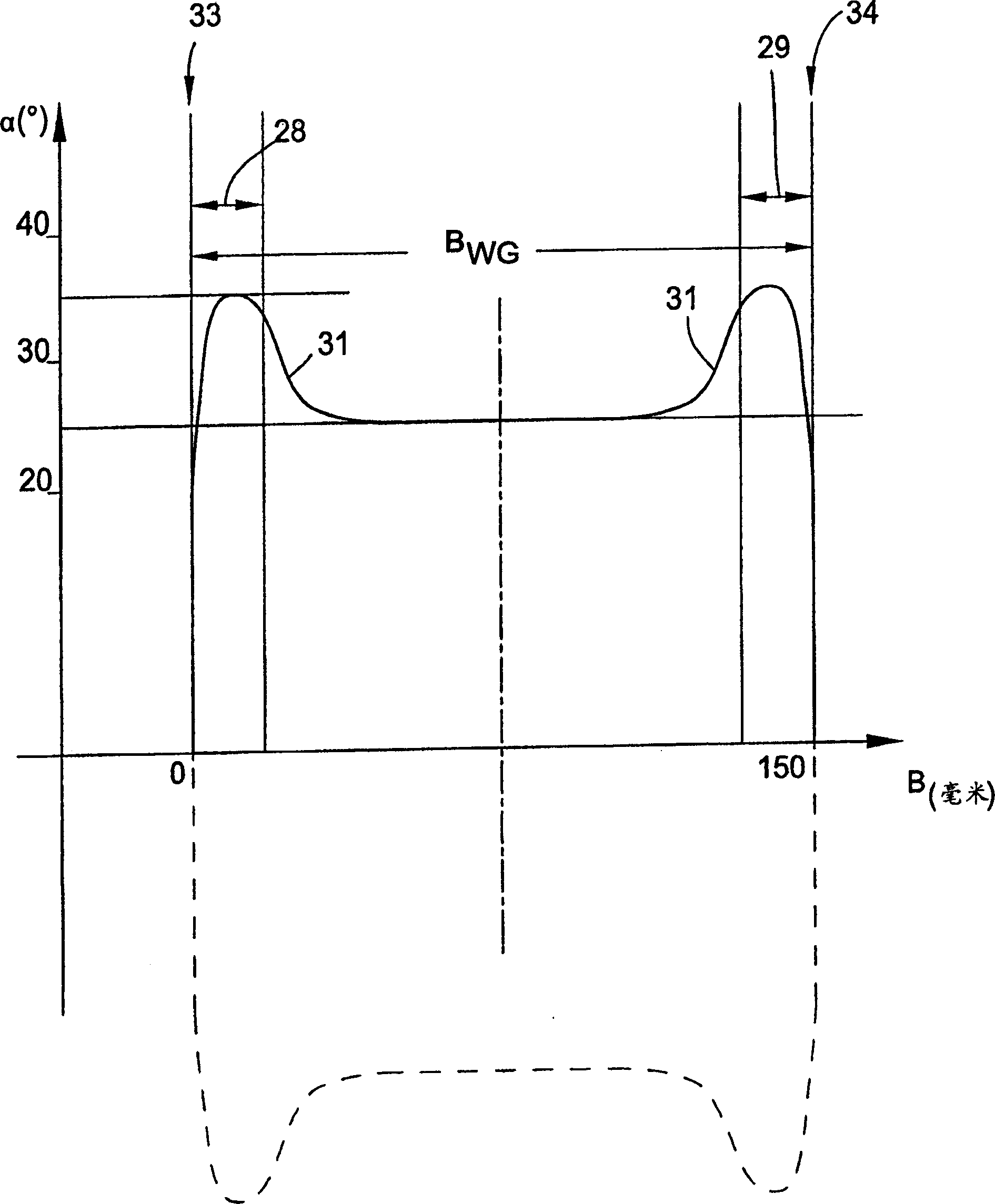
A method for forming a conical cross-wound bobbin by rotor spinning yarn by the following winding the yarn package, that is in a winding process, a crossing angle alpha in the middle section is smaller than that of the other parts of the winding process, and an across alpha M is created between 15-28 degrees in the middle zone, which is produced with this angle across alpha M more than 50% of the total winding width B WG.

Description

technical field [0001] The invention relates to a conical bobbin in which the intersection angle α in the middle region of the winding stroke in each layer is smaller than in the other parts of the winding stroke. The invention also relates to a method for guiding yarn to form a conical package, wherein the yarn is guided such that within a winding stroke, the angle of intersection α is smaller in the middle region of the winding stroke than at the rest of the winding stroke. part. Background technique [0002] The yarn produced by the rotor spinning machine is different from the ring-spun yarn in terms of package structure and unwinding performance. Rotor-spun yarn has less hairiness than ring-spun yarn, so it can be unwound better (easier to lift), but it has a greater rolling tendency than ring-spun yarn, so the yarn at the edge of the package is overlapped The layers are squeezed out. This results in an excess of the normal winding stroke of eg 150 mm up to a cross-wo...

Claims


Application Information

Patent Timeline
Patent Type & Authority Patents(China)
IPC IPC(8): B65H54/10B65H55/04D01H1/36B65H54/38
CPCB65H54/385B65H55/04B65H2701/31
Inventor H·-D·格贝尔斯G·格巴尔德F·舍尔
Owner SAURER GERMANY GMBH & CO KG
Learn More