Columnar tube and rolling method thereof

A cylindrical and bobbin technology, applied in the field of cylindrical bobbin packages, can solve the problems of bobbin revolution fluctuation and uncontrollability, and achieve the effects of high yarn unwinding speed, entanglement prevention, and end face structure improvement.

Inactive Publication Date: 2003-07-02
SAURER GERMANY GMBH & CO KG
View PDF3 Cites 1 Cited by
  • Summary
  • Abstract
  • Description
  • Claims
  • Application Information

AI Technical Summary

Problems solved by technology

Since the length of the cone circumference of the cone differs from the axis of the cone, the conical cone for winding comes into contact with the parts on the left and right of the drum drive close to the predetermined friction zone as the diameter of the cone increases. , resulting in fluctuations in the number of revolutions of the bobbin and uncontrollable

Method used


Image

  • Columnar tube and rolling method thereof
  • Columnar tube and rolling method thereof
  • Columnar tube and rolling method thereof

Examples


Embodiment Construction

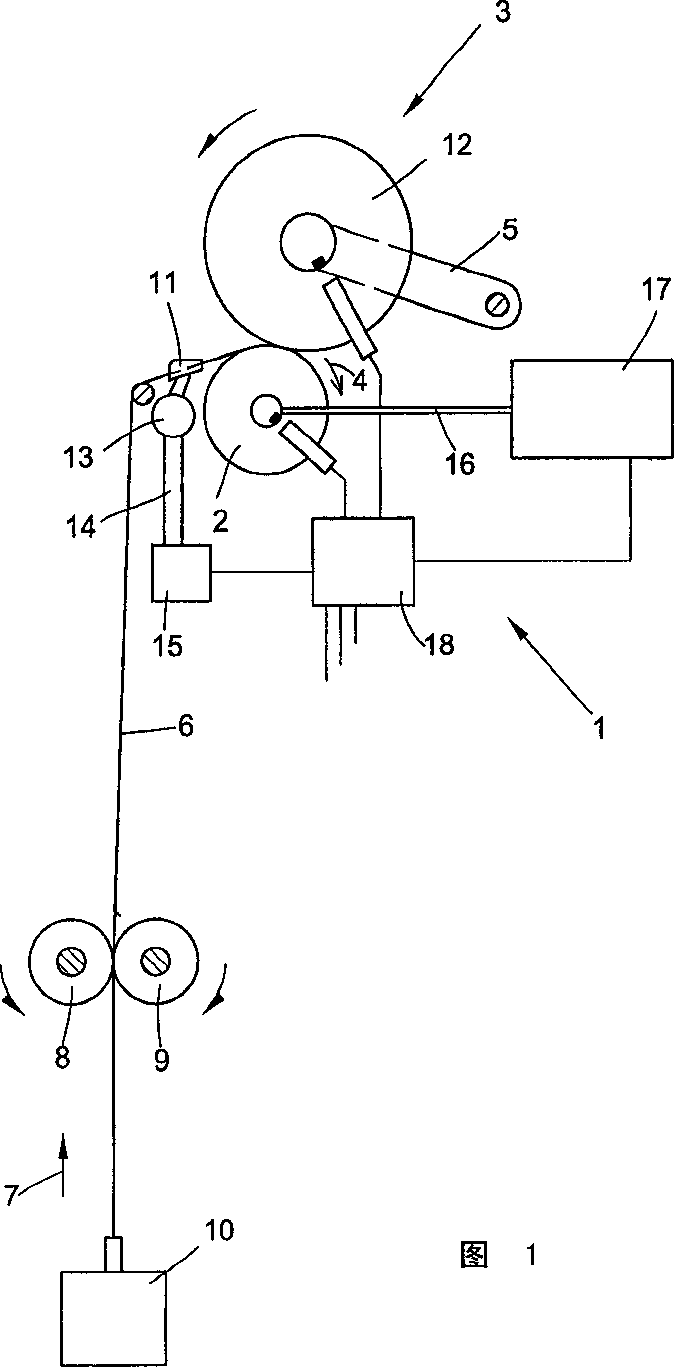
[0024] Figure 1 shows a winding device for the production of cylindrical packages on a rotor spinning machine. The winding device 1 has a drum 2 which drives a cylindrical bobbin 3 by means of friction. Drum 2 rotates in the direction of arrow 4. The bobbin 3 is supported by a rotatable bobbin holder 5 and rests against the drum 2 . Roller 2 is under pressure. The yarn 6 is drawn in the direction of the arrow 7 by means of cooperating yarn delivery roller pairs 8, 9 from the spinning box 10 of the spinning position at a constant yarn speed and is wound into a bobbin by means of a reciprocating yarn guide 11 3 of cylindrical windings 12 . The yarn guide 11 is a part of the reciprocating mechanism 13, which is connected to the motor 15 through an effective connector 14, and is driven by the motor. The drum 2 is driven by the shaft of the motor 17 . The motors 15 and 17 are all controlled by a microprocessor 18, where the intersection angle α of the cylindrical bobbin 3 is r...


PUM


Abstract

A winding method for forming a cylindrical shape bobbin is provided, whereby, an intersection angle (alpha) is varying while the yarn is winded. To guide yarn, a yarn intersection angle (alpha M) at the center zone in the bobbin winding process is between 15-28 degrees and the yarn intersection angle (alpha R) towards the edge zones of two ends of the winding package is larger than that of the center zone.

Description

technical field [0001] The invention relates to a cylindrical bobbin and a method for forming a cylindrical bobbin package with a guide yarn as described in the preamble of claims 1 and 7 . Background technique [0002] The yarn produced by the rotor spinning machine is different from the ring-spun yarn in terms of package structure and unwinding performance. Rotor-spun yarn has less hairiness than ring-spun yarn, so it can be unwound better (easier to lift), but it has a greater rolling tendency than ring-spun yarn, so the yarn at the edge of the package is overlapped The layers are squeezed out. This results in a cross-wound bobbin over a normal winding stroke of eg 150 mm up to a width of 170 to 180 mm. In this case, the required bobbin structure with flat end faces is no longer maintained. This phenomenon occurs in natural fiber yarns, such as cotton yarns, especially in coarse-count yarns, and the thicker the yarn counts, the more prominent the phenomenon. [0003] ...

Claims


Application Information

Patent Timeline
Patent Type & Authority Applications(China)
IPC IPC(8): B65H54/06B65H54/38B65H55/04
CPCB65H54/385B65H55/04B65H2701/31
Inventor H·-D·格贝尔斯G·格巴尔德F·舍尔
Owner SAURER GERMANY GMBH & CO KG
Why Eureka
Try Eureka