Plate-mounting device

A technology for installing devices and printing plates, which is applied in printing, printing machines, printing processes, etc., and can solve problems such as difficult installation of plate-shaped printing plates, position deviation, etc.

Inactive Publication Date: 2006-09-06
LINTEC CORP
View PDF0 Cites 0 Cited by
  • Summary
  • Abstract
  • Description
  • Claims
  • Application Information

AI Technical Summary

Problems solved by technology

[0003] In this case, it is not easy to accurately mount a plate-like printing plate on the outer peripheral surface of a cylindrical printing plate cylinder
That is, there is a disadvantage that when mounted on the outer peripheral surface of the plate cylinder, there will be a positional deviation from the precise position of the outer peripheral surface of the plate cylinder in the axial or circumferential direction

Method used


Image

  • Plate-mounting device
  • Plate-mounting device
  • Plate-mounting device

Examples


Embodiment Construction

[0016] Preferred embodiments of the present invention will be described below with reference to the accompanying drawings.

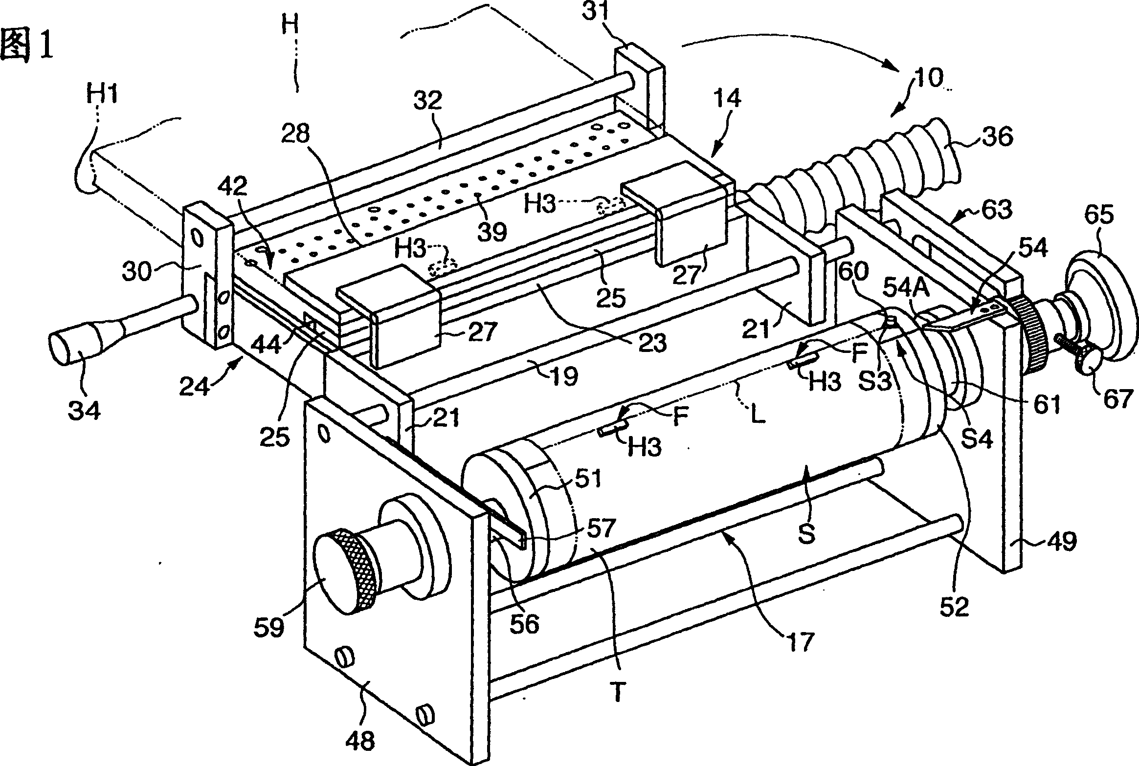
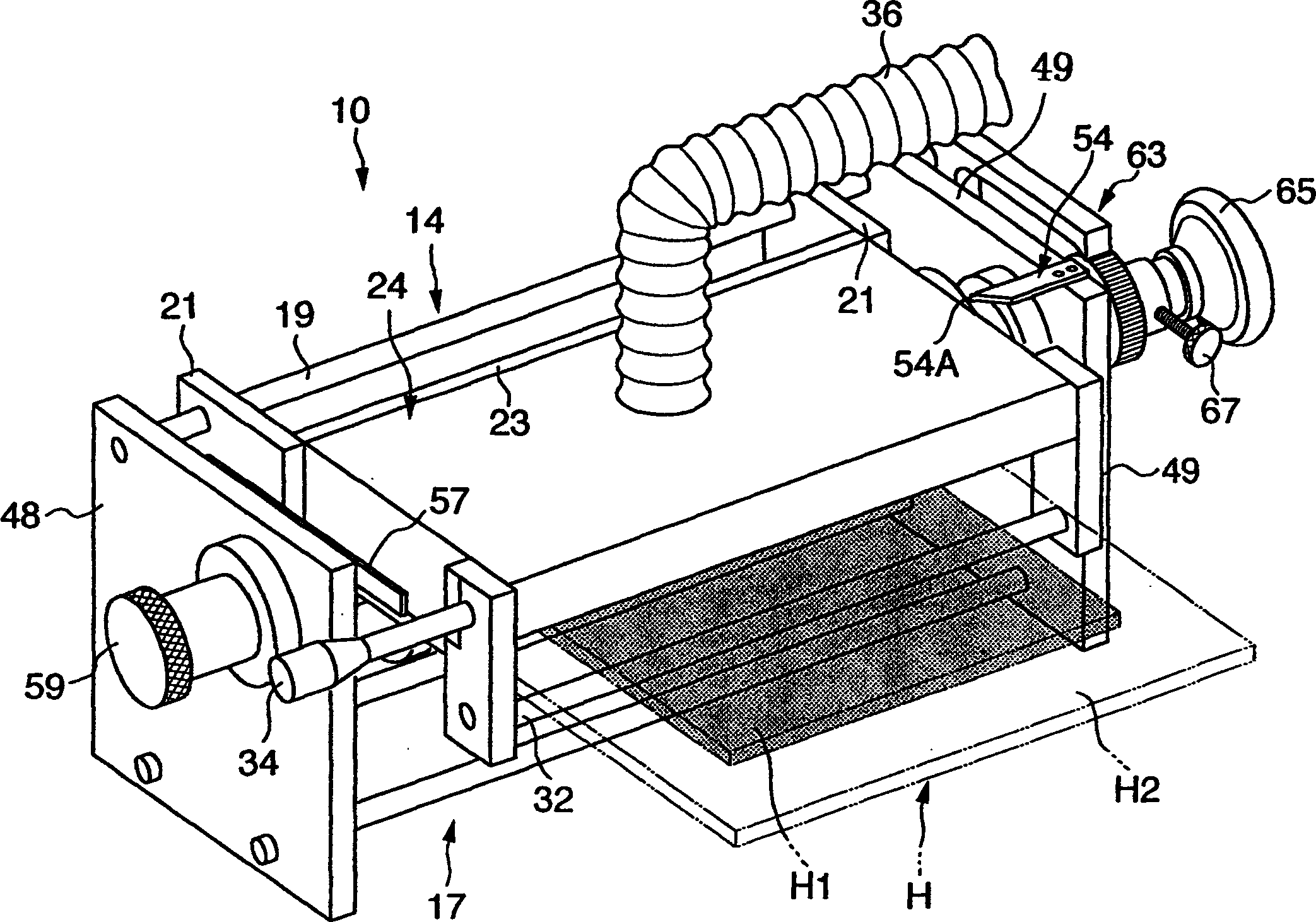
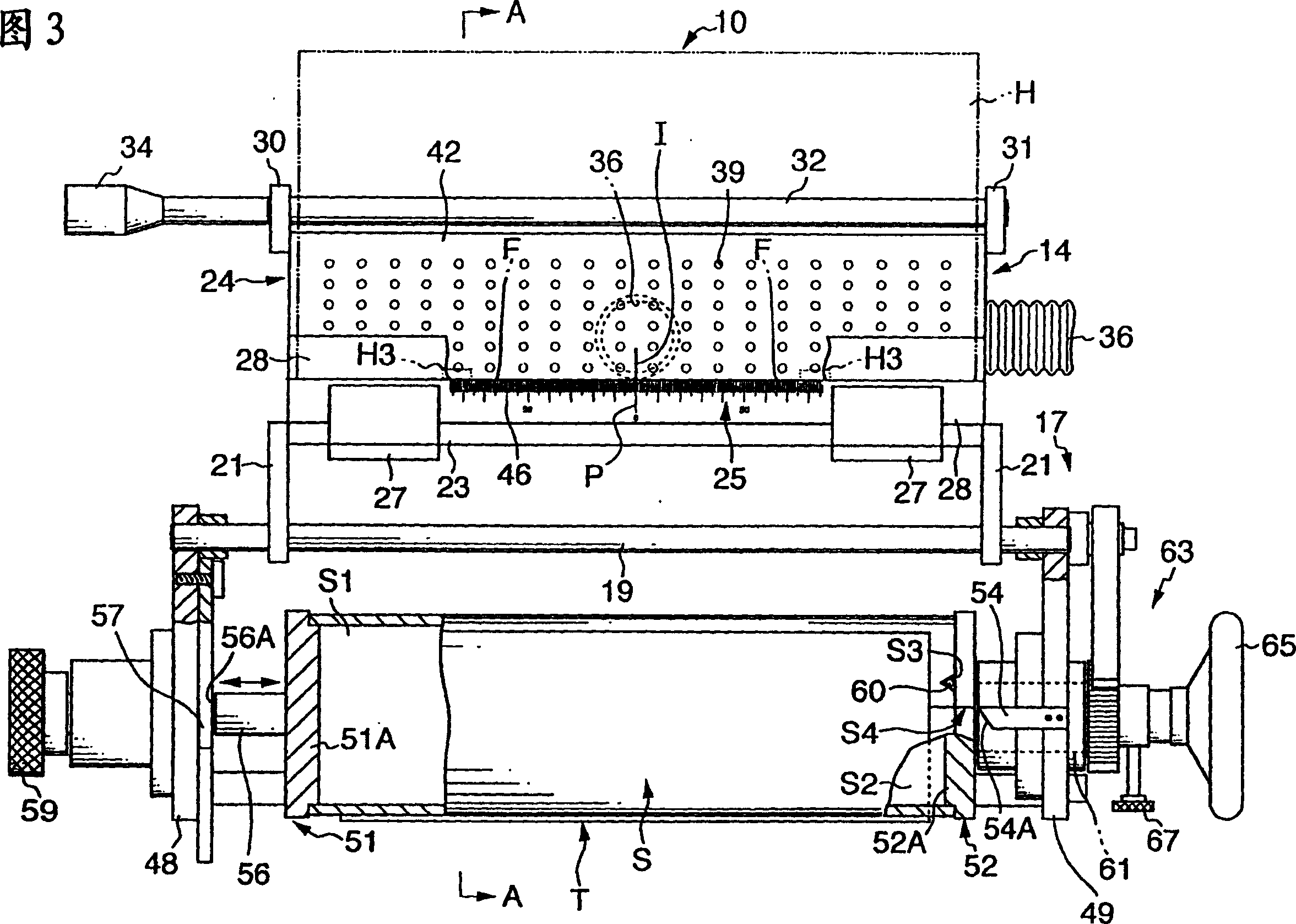
[0017] FIG. 1 is a schematic perspective view of a state of a printing plate mounting apparatus 10 according to the present invention. figure 2 is a schematic perspective view of another state of the printing plate mounting device 10 . FIG. 3 is a schematic plan view of the printing plate mounting device 10 shown in FIG. 1 . Figure 4 is a sectional view of the plate mounting apparatus 10 taken along line A-A of FIG. 3 , wherein a part of the apparatus shown in FIG. 3 is omitted. The printing plate mounting device 10 shown in these figures is a device for mounting a printing plate H on the outer peripheral surface of a printing plate cylinder S which has been printed from a printing machine (not shown). Remove from the device. The printing plate mounting device 10 has a printing plate setting portion 14 for holding the printing plate H, and a printing...


PUM


Abstract

A press plate mounting apparatus (10) has a press plate placement portion (14) capable of holding a press plate (H) having a partially formed print face region (H1), and a plate cylinder holding portion (17) that rotatably holds a plate cylinder (S) onto which the press plate is mounted. Positioning cross marks (H3) are provided in a non-print region (H2) of the press plate. The press plate placement portion includes a suction surface (42) that sucks the print face region, and a scale member (46) provided at a position outward of the suction surface and extending in a predetermined direction. The scale member is able to contact the locating cross marks when the press plate is held at a predetermined position. The scale member has a scale that makes it possible to visually check a positional deviation of the press plate in the predetermined direction.

Description

technical field [0001] The present invention relates to a printing plate mounting device, and more particularly to a printing plate mounting device capable of easily and accurately mounting a printing plate on the outer peripheral surface of a printing plate cylinder. Background technique [0002] A rotary-imprinting, generally cylindrical, plate cylinder is designed such that a plate-like printing plate having raised and recessed printing surface areas can be mounted to the peripheral surface of the plate cylinder. The plate cylinder installation operation is in many cases performed manually. [0003] In this case, it is not easy to accurately mount a plate-like printing plate on the outer peripheral surface of a cylindrical printing plate cylinder. That is, there is a disadvantage that, when mounted on the outer peripheral surface of the printing plate cylinder, there is a positional deviation from the precise position of the outer peripheral surface of the printing plate...

Claims


Application Information

Patent Timeline
IPC IPC(8): B41F27/00B41L29/00B41F27/12
CPCB41F27/005Y10S101/36B41F27/1212B41F27/00
Inventor 长田一夫塚本胜秀
Owner LINTEC CORP
Why Eureka
Try Eureka