Feeder for polyhedron inspection and polyhedron inspector

A technology for testing equipment and polyhedrons, which is applied in semiconductor/solid-state device manufacturing, instruments, transportation and packaging, etc. It can solve problems such as large equipment size, conveyors that cannot be arranged in a straight line, and complex structures, and achieve reliable inspection results.

Inactive Publication Date: 2006-09-06
LINTEC CORP
View PDF1 Cites 2 Cited by
  • Summary
  • Abstract
  • Description
  • Claims
  • Application Information

AI Technical Summary

Problems solved by technology

[0004] However, the above-mentioned apparatus requires a mechanism for reversing the inspected articles between the first and second conveyors; thus causing problems such as complicated structure
In addition, in order to invert the inspection items, the first and second conveyors cannot be arranged in a straight line; therefore, a predetermined space is required in the vertical direction as the arrangement space of the conveyors, causing problems such as large equipment size

Method used


Image

  • Feeder for polyhedron inspection and polyhedron inspector
  • Feeder for polyhedron inspection and polyhedron inspector
  • Feeder for polyhedron inspection and polyhedron inspector

Examples


Embodiment Construction

[0031] An embodiment of the present invention will be described below with reference to the accompanying drawings.

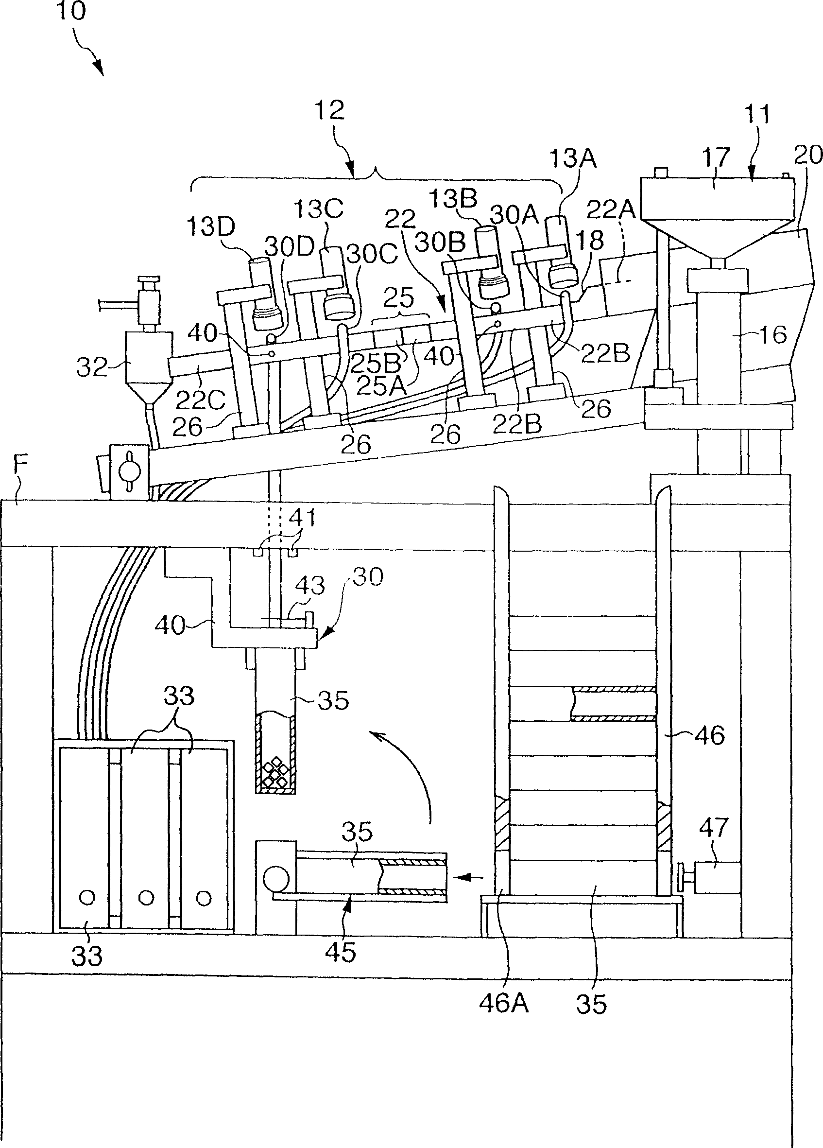
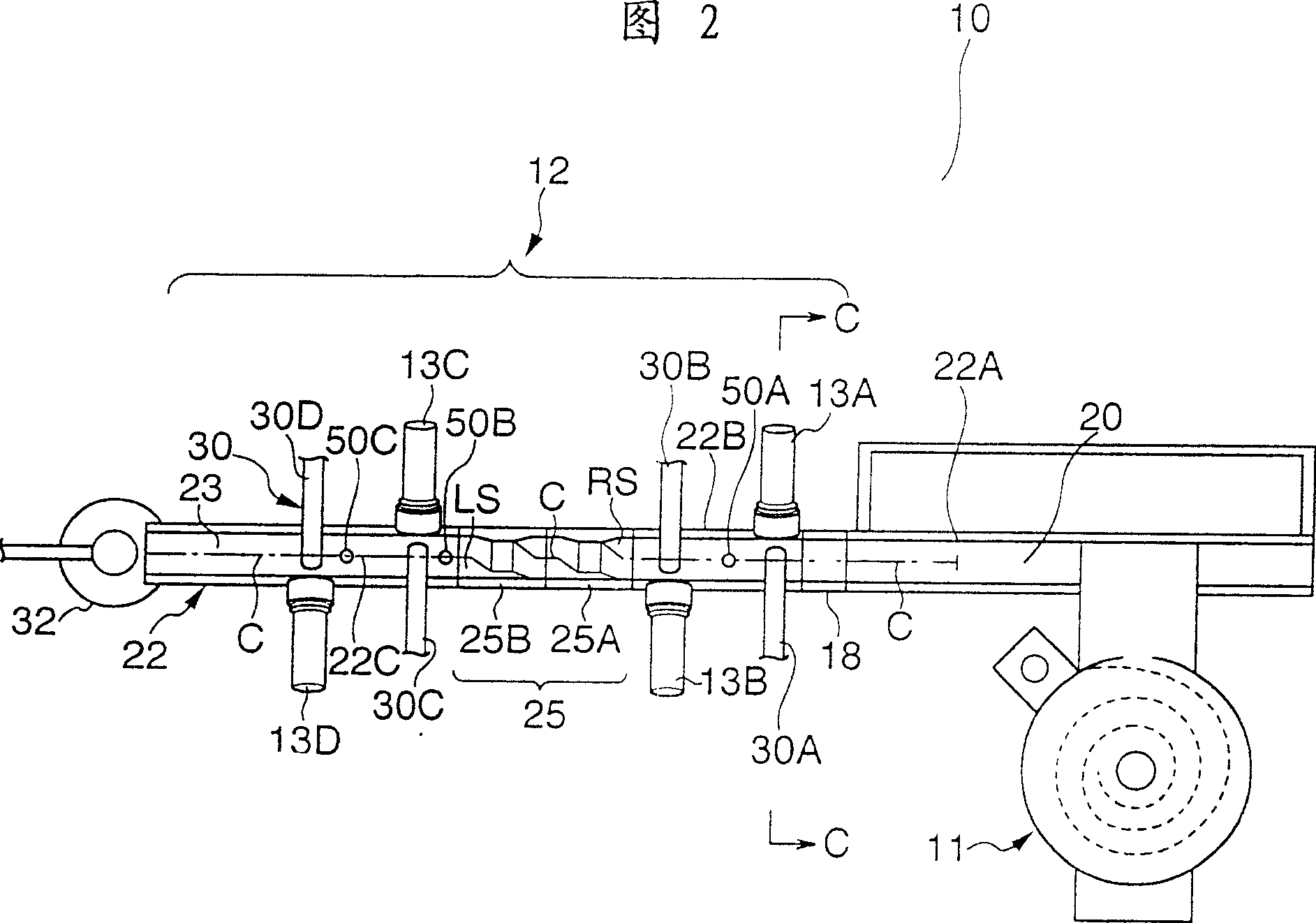
[0032] figure 1 The front view of Fig. 2 schematically represents the overall structure of the polyhedron inspection equipment of the present invention, and the top plan view of Fig. 2 represents figure 1 Major parts of the polyhedron inspection equipment shown. like figure 1 As shown in FIG. 2, the polyhedron inspection apparatus 10 includes a supply unit 11, a polyhedron inspection feeder 12 (see FIG. 2), first to fourth cameras 13A to 13D serving as inspection means, and a recovery unit 30. More specifically, a supply device 11 is provided on an upper portion of one frame F, and a polyhedron inspection feeder 12 moves inspection items supplied from the supply device 11, which in this embodiment are cubic ceramic block capacitors (hereinafter referred to as Pellet W). First to fourth cameras 13A to 13D are arranged above the polyhedron inspection feeder 12...


PUM


Abstract

A polyhedron inspector (10), comprising a feeder for polyhedron inspection (12) having a passage forming member for inspecting the surfaces of chips (W) in cubic shape, the feeder for inspection polyhedron (12) further comprising generally V-shaped grooves formed therein and two rotatingly feeding parts (25A, 25B) disposed in the passage forming member (22), wherein the rotatingly feeding parts (25A, 25B) are formed in the cross sections of generally V-, U-, and V-shapes arranged in that order, and a chuter (18) for moving the chips (W) one by one apart from each other, cameras (13A to 13D) for inspecting the surfaces of the chips (W) and a recovery means (30) for recovering the chips (W) depending on the inspection results are fitted to the passage forming member (22).

Description

technical field [0001] The present invention relates to a polyhedron inspection feeder and a polyhedron inspection apparatus, and more particularly, to a polyhedron inspection feeder and a polyhedron inspection apparatus suitable for inspecting the surface accuracy of inspection objects such as electronic component pellets. Background technique [0002] Conventionally, in the case of inspecting the precision of processed surfaces of electronic components such as pellets, each surface of these pellets is inspected by a worker using a magnifying glass. However, in the above-mentioned inspection, workers hold the pellets one by one with their hands and then inspect them with eyes; therefore, defects such as minute scratches and deformations are overlooked in many cases. Therefore, this is a factor of mixing defective products into the product. In addition, due to fatigue due to inspection work, the work load is heavy. In addition, there is also a problem that the precision in...

Claims


Application Information

Patent Timeline
Patent Type & Authority Patents(China)
IPC IPC(8): B65G47/22B07C5/02G01N21/89B07C5/342H01L21/00
CPCB07C5/02B07C5/342H01L21/67271G01B11/24
Inventor 木村孝木川一洋
Owner LINTEC CORP
Why Eureka
Try Eureka