Electromagnetic brake

An electromagnetic brake and movement technology, applied in the direction of brake types, drum brakes, brake components, etc., can solve problems such as difficulty in clamping shock absorbing pads, reduced attractive force, and complex collision surfaces

Inactive Publication Date: 2006-09-27
MITSUBISHI ELECTRIC CORP
View PDF0 Cites 0 Cited by
  • Summary
  • Abstract
  • Description
  • Claims
  • Application Information

AI Technical Summary

Problems solved by technology

[0011] However, making the impact surface into a stepped shape in this way makes the impact surface complicated and it is difficult to sandwich the impact absorbing pad.
A gap is required so that the collision surface does not touch, so the surface where the magnetic attraction works is reduced, and the attractive force is reduced

Method used


Image

  • Electromagnetic brake
  • Electromagnetic brake
  • Electromagnetic brake

Examples


Embodiment Construction

[0027] Hereinafter, embodiments of the present invention will be described with reference to the accompanying drawings. In addition, in each figure, the same code|symbol is attached|subjected to the same or corresponding part, and the description is simplified or omitted.

[0028] First, from Figure 1 to Figure 8 Embodiment 1 of the present invention will be described.

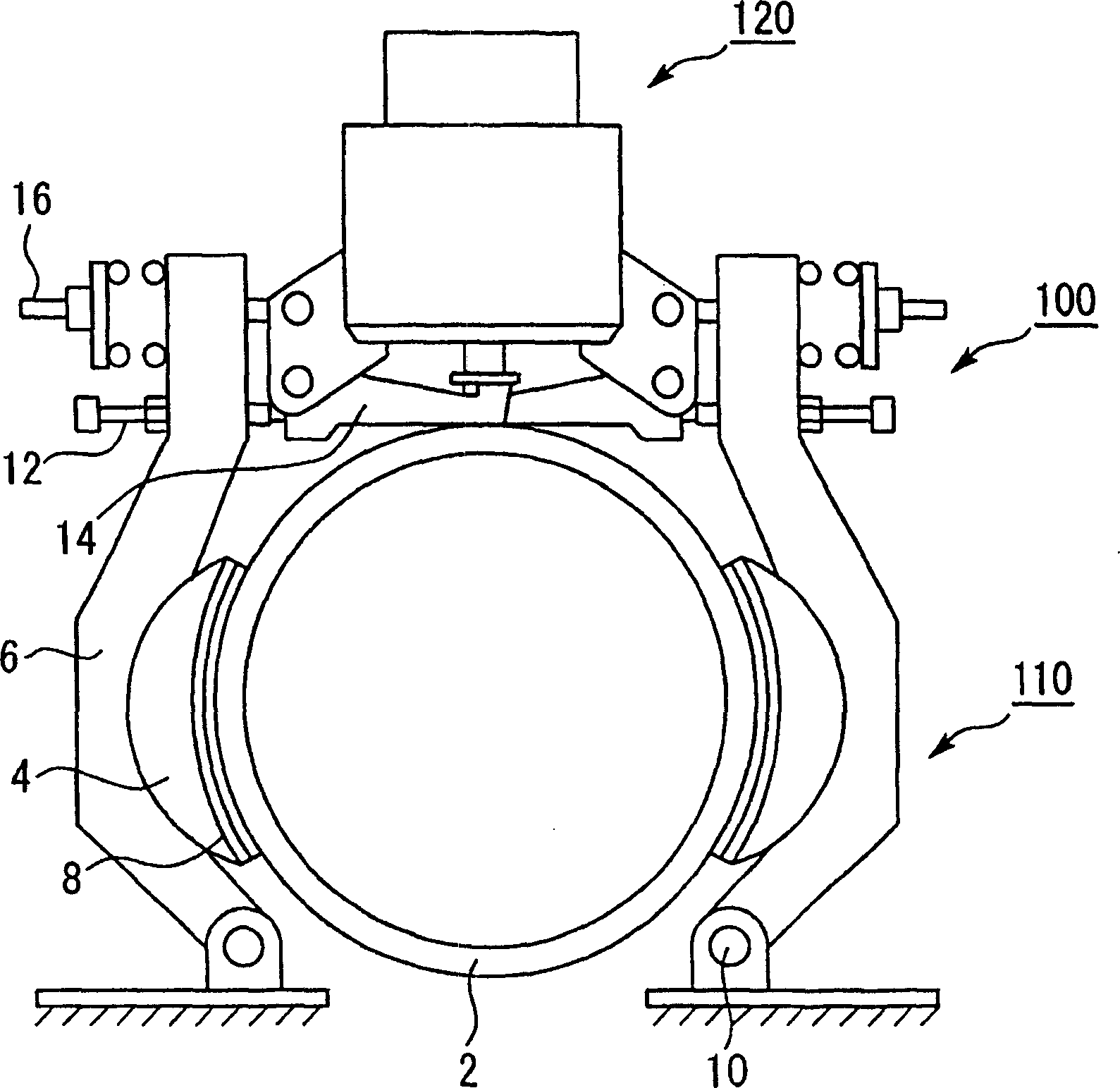
[0029] figure 1 It is a front view illustrating the brake 100 for a hoist according to Embodiment 1 of the present invention.

[0030] Such as figure 1 As shown, the brake 100 for a hoist has a brake mechanism 110 and a plunger type solenoid valve 120 .

[0031] The brake mechanism 110 is composed of a brake drum 2 , a brake pad 4 , and a brake arm 6 .

[0032] The brake drum 2 is attached to a motor shaft (not shown) of the brake 100 for a hoist. The brake drum 2 is a circular cylindrical body viewed from the front. The brake pads 4 are disposed opposite to each other at two opposing places on the o...


PUM


Abstract

The electromagnetic brake incldues fixed iron core, movable iron core opposite to one side of the fixed iron core, and winding to make the movable iron core move to alter the distance between the opposite sides of the fixed iron core and the movable iron core. There are at least two notches in the opposite sliding slides of the fixed iron core and the movable iron core for braking.

Description

technical field [0001] The present invention relates to electromagnetic brakes. More specifically, it is preferably an elevator electromagnetic brake disposed in a hoist for a rope elevator. Background technique [0002] Figure 10 It is a front view which shows the brake 300 for conventional hoists. Figure 11 It is a cross-sectional view showing an example of a plunger type solenoid valve used in a conventional elevator brake. [0003] Such as Figure 10 As shown, the brake 300 for a hoist is composed of a brake mechanism 310 and a plunger type solenoid valve 320 . [0004] The brake mechanism 310 has the brake drum 2 connected to the motor (not shown) of the brake 300 for hoists. Brake pads 4 are provided at two opposite places on the outer peripheral wall of the brake drum 2 . The brake arm 6 is connected to the brake pad 4 . The lower end of each brake arm 6 is fixed with an arm pin 10 . The top of each brake arm 6 is connected with a brake lever 14 with a stop bo...

Claims


Application Information

Patent Timeline
Patent Type & Authority Patents(China)
IPC IPC(8): F16D65/34F16D65/18F16D49/16H01F7/16F16D65/14F16D65/28H01F3/14H01F7/08
CPCF16D49/16F16D65/14F16D2121/20F16D2125/64H01F3/14H01F7/081H01F7/1607H01F2007/086
Inventor 小松孝教大榖晃裕
Owner MITSUBISHI ELECTRIC CORP
Why Eureka
Try Eureka