Source driving device for intracavitary tumour after-mounted radiotherapy machine
A radiation therapy and source-driven technology, which is applied in X-ray/γ-ray/particle irradiation therapy, etc., can solve problems such as troublesome assembly, commissioning and maintenance, high manufacturing cost, and slipping, so as to improve the reliability and accuracy of source drive and avoid pulling Growth and fracture phenomenon, the effect of reducing manufacturing cost
- Summary
- Abstract
- Description
- Claims
- Application Information
AI Technical Summary
Problems solved by technology
Method used
Image

Examples
Embodiment Construction
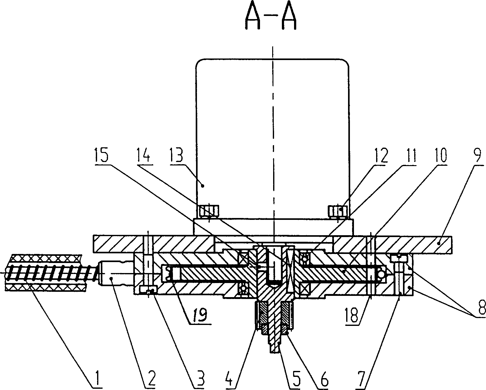
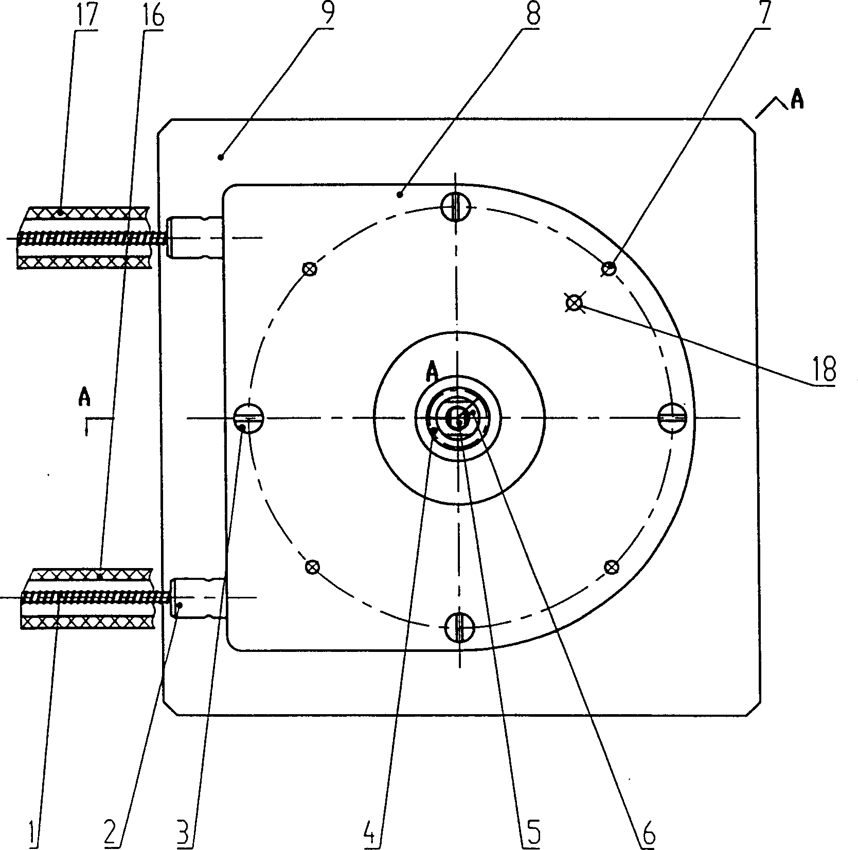
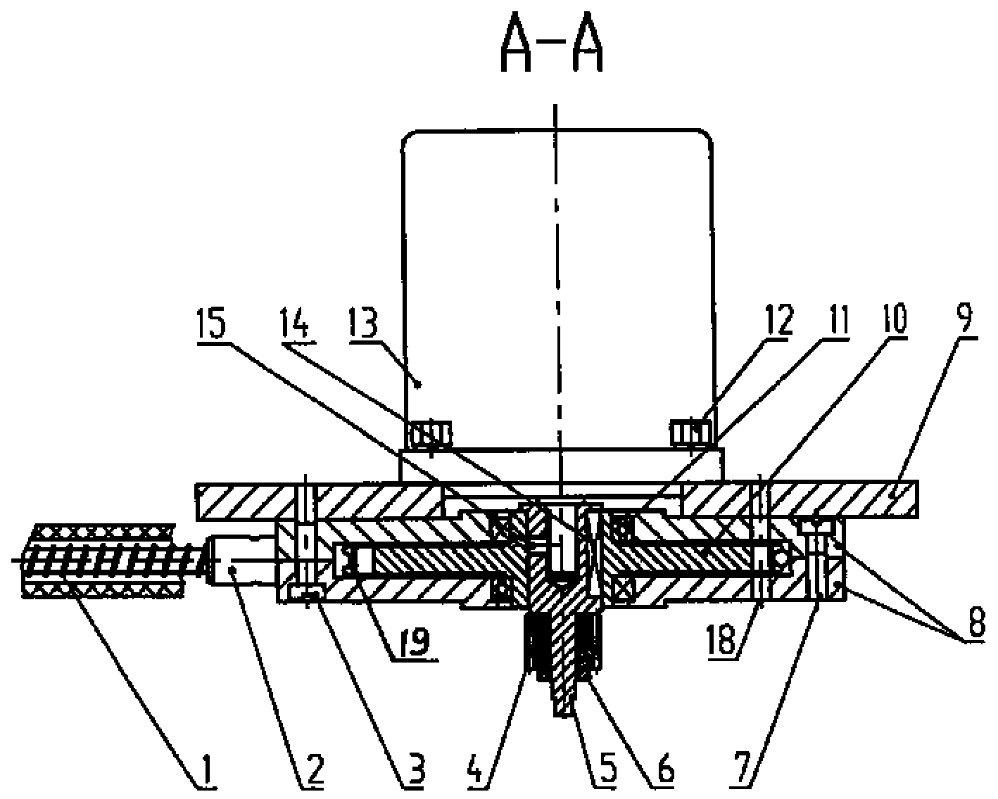
[0010] Now in conjunction with accompanying drawing and embodiment the present invention is described in detail:
[0011] Such as figure 1 , figure 2 As shown, the source braided control cable 1 of the source driving device in the present invention adopts a steel wire rope as a mandrel, and then tightly winds a layer of helical steel wire on the steel wire rope to make it. The helix angle γ is 13.15°, and the pitch P1 is 2.5mm. One end of the source braid control cable 1 is connected to the radiation source braid, and the other end is meshed with the helical gear 10 . The helix angle β of the helical gear is 13.15°, and the tooth pitch P2 is 2.5 mm. An annular arc groove 19 with a radius of 1.8 mm is opened on the symmetrical middle surface of the helical gear 10 in the tooth width direction. The serial movement of the source braided control cable 1 in the tooth width direction of the helical gear 10 can be restricted. The helical gear 10, the casing 8, the bearing 11, an...
PUM
| Property | Measurement | Unit |
|---|---|---|
| Radius | aaaaa | aaaaa |
Abstract
Description
Claims
Application Information
PatSnap Eureka turns technology decisions into work you can execute. Powered by our Innovation Knowledge Graph, it runs expert workflows across engineering, life sciences, materials and intellectual property. Get your review-ready output in minutes.


