Lighting system for a bicycle

a technology for bicycles and light fixtures, applied in bicycle equipment, lighting and heating apparatus, optical signals, etc., can solve the problems of battery systems, heavy weight, run-time, and cost, and achieve the effect of low weight, high efficiency, and high efficiency of power converters

Inactive Publication Date: 2006-12-05
KOHARCHECK ALAN WILLIAM
View PDF23 Cites 24 Cited by
  • Summary
  • Abstract
  • Description
  • Claims
  • Application Information

AI Technical Summary

Benefits of technology

[0007]The present invention is directed to a bicycle lighting system that is long lasting, low weight, highly efficient, and powered by a generator driven by a drive wheel rolling against a portion of the rear wheel. A highly efficient power converter and generator provide high light output from low to high speeds. Operation at high speeds is possible without the system becoming damaged, light output being affected, or significant amounts of drag being placed on the bike in the form of electromechanical inefficiency as is the standard practice in conventional systems.
[0008]The invention provides a mechanism that is attached to the frame at two points: the brake caliper pivot and the rear axle. These two locations are common in many modern bikes thus providing for a universal fit and quick and simple removal or attachment of the mechanism. In addition, a small onboard battery provides light during periods when the bike is stationary and a charging system that keeps the battery charged.
[0009]One embodiment of the invention is a lighting system for a bicycle having a bicycle frame and at least two wheels. The lighting system includes a structural beam mounted to a portion of the bicycle frame. A generator is mounted to the beam such that the beam holds the generator in position to be frictionally driven by contact with a portion of the rear wheel. The generator provides a three-phase output voltage. A sensor monitors the generator and provides an output signal proportional to the speed of the bicycle. A first sensing circuit receives the output signal from the sensor and provides a first control signal when the output signal exceeds a first predetermined value operative to change the output voltage from the three-phase voltage to a single-phase voltage to thereby prevent damage to the system.
[0010]Another embodiment of the invention is a voltage control system for a bicycle having a bicycle frame and at least two wheels. The voltage control system includes a three-phase generator driven by frictional engagement against a wheel of the bicycle. The generator provides a three-phase output voltage in the form of sine waves with positive and negative halves. A three-phase full-bridge rectifier receives the three-phase output voltage of the generator and inverts the negative halves of the sine waves generated. The rectifier provides a DC output voltage proportional to a three-phase line-to-line voltage. A DC-to-DC converter changes the DC output voltage from the rectifier to a first working voltage. A lamp attached to a portion of the bicycle receives the first working voltage from the converter, and a sensor monitors the generator and provides an output signal proportional to the speed of the bicycle. A first sensing circuit receives the output signal from the sensor and provides a first control signal at a first predetermined value of the output signal from the sensor. A first relay connected between the generator and the rectifier is connected to the first sensing circuit to receive the first control signal. The first relay, during a state of increasing bicycle speed, changes the output voltage of the generator from the three-phase line-to-line voltage to a single-phase line-to-neutral voltage when the first control signal is received from the first sensing circuit, thereby reducing the DC output voltage from the rectifier to avoid damage to the converter while supplying the first working voltage to the lamp.

Problems solved by technology

Weight, run-time, and cost all become limiting performance factors.
A long lasting battery is often heavier and more costly.
A key problem with battery systems is maintenance.
Typically, the battery must be recharged after each use, and this often takes a significant amount of time of up to 4 times longer than the use of the battery.
In addition, a remote battery charger must usually be utilized to charge the battery, which adds to the inconvenience of battery systems.
Conventional generator systems are currently more limited in use, and the models that are offered have several drawbacks.
Such systems are inefficient in their drive systems including their power output and power conversion.
They do not offer different power delivery solutions for stationary performance, low speed performance and high speed performance.
Conventional generator systems are typically not easy to remove and replace.
Conventional tire driven generator systems are noisy and rough, and their designs typically add to the inefficiency of the overall lighting system.
Inadequate light levels and excessive drag on the bicycle are typical.

Method used


Image

  • Lighting system for a bicycle
  • Lighting system for a bicycle
  • Lighting system for a bicycle

Examples


Embodiment Construction

[0033]Reference will now be made to the drawings wherein like numerals refer to like parts throughout.

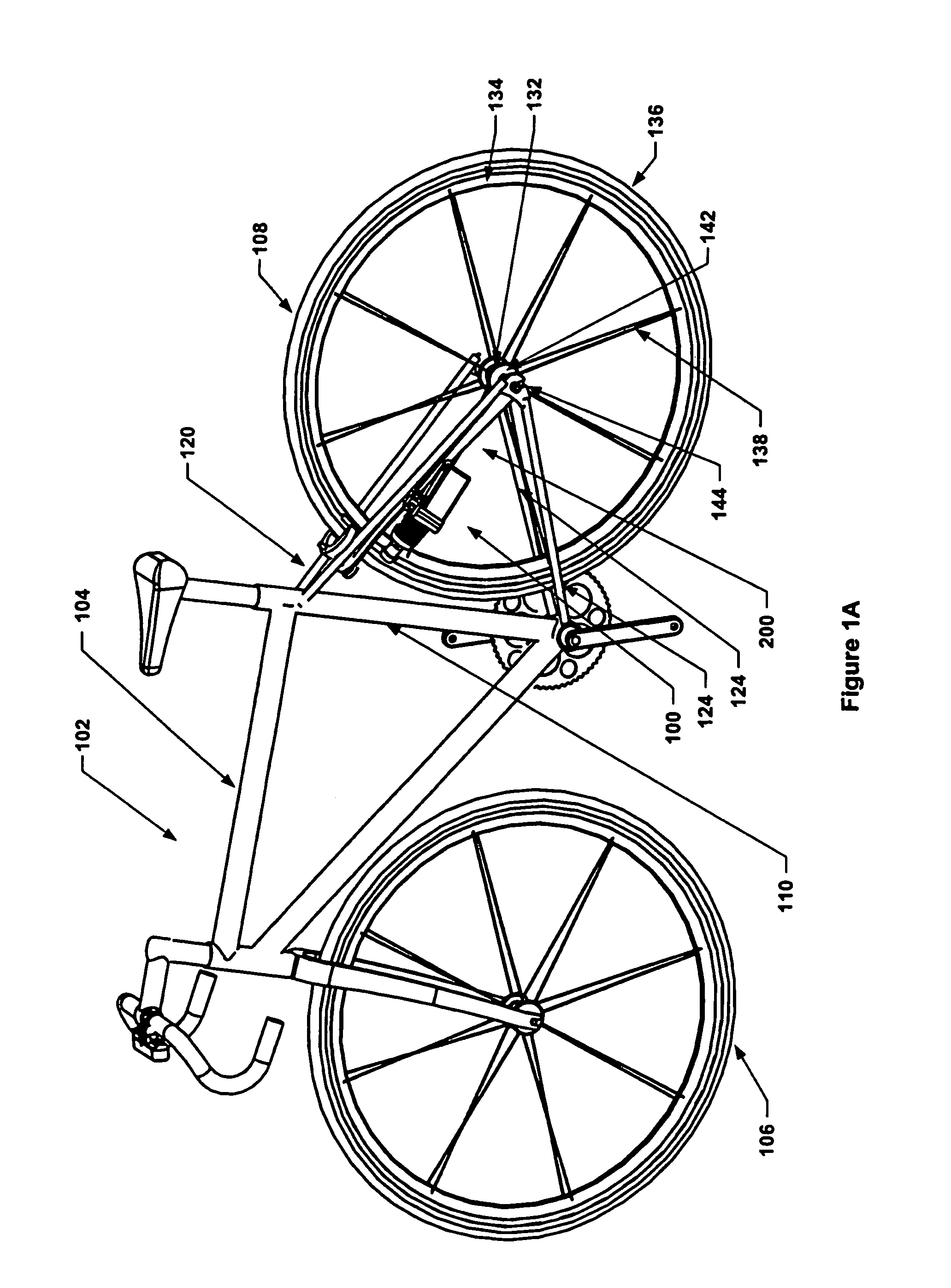
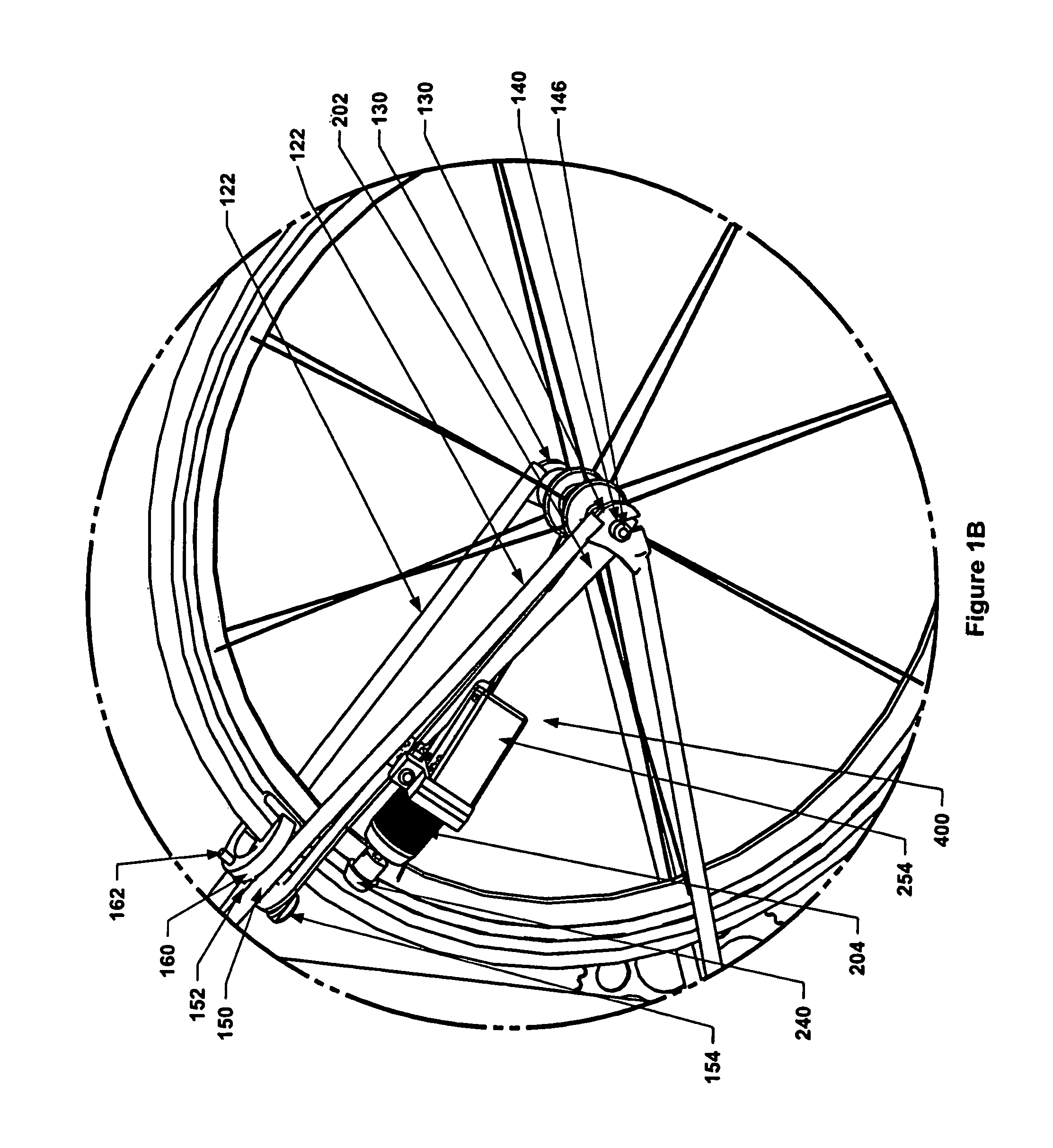
[0034]FIG. 1A illustrates one embodiment of a lighting system 100 for a bicycle 102 having a bicycle frame 104 and front and rear wheels 106, 108. FIG. 1B is another side perspective view of the lighting system of FIG. 1A. Frame 104 includes a seat post 110 and one or more rear struts 120 extending from seat post 110. Struts 120 support rear wheel mounts 130 for mounting rear wheel 108 to frame 104. Rear struts 120 include upper and lower arms 122, 124 that extend from seat post 110 towards each other to be joined at rear wheel mounts 130. Bicycle 102 may comprise a road bike, mountain bike or any other type of cycle.

[0035]Rear wheel 108 comprises rear axle 132, rear rim 134, and rear tire 136. Rear tire 136 is mounted to rim 134, and rim 134 is attached to axle 132 via a plurality of spokes 138.

[0036]Rear axle 132 includes a shaft 140 that extends through a central portion of a bod...


PUM


Abstract

A lighting system for a bicycle. A lamp and a beam are mounted to the bicycle. A generator is mounted to the beam such that the beam holds the generator in position to be frictionally driven by contact with a bicycle wheel. The generator provides a three-phase output voltage. A sensor monitors the generator and provides an output signal proportional to the speed of the bicycle. A first sensing circuit receives the output signal from the sensor and provides a first control signal when the output signal exceeds a first predetermined value. The first control signal is operative to change the output voltage from the three-phase output voltage to a single-phase output voltage to prevent damage to the system.

Description

BACKGROUND OF THE INVENTION[0001]1. Field of the Invention[0002]The present invention relates to a lighting system for a bicycle.[0003]2. Description of Related Art[0004]Current lighting systems for bicycles are powered by batteries or generators with batteries being most common. In battery-powered systems, headlamps provide light output with the higher performance lamps demanding more power, size, and cost. The battery must be of significant size to provide the necessary power over the length of time needed. Weight, run-time, and cost all become limiting performance factors. A long lasting battery is often heavier and more costly. In general, battery systems are conveniently removed, and they provide necessary light output over a limited time frame. A key problem with battery systems is maintenance. Typically, the battery must be recharged after each use, and this often takes a significant amount of time of up to 4 times longer than the use of the battery. In addition, a remote bat...

Claims


Application Information

Patent Timeline
Patent Type & Authority Patents(United States)
IPC IPC(8): B62J6/00B62M1/36
CPCB62J6/001B62J6/08B62J6/01
Inventor KOHARCHECK, ALAN WILLIAMRATZLOFF, JEFFREY KENNETH
Owner KOHARCHECK ALAN WILLIAM
Why Eureka
Try Eureka