
High-pressure piston cylinder and high-pressure transportation pump of internal-combustion engine

A high-pressure conveying, high-pressure piston technology, applied in the components of the pumping device for elastic fluid, fuel injection pump, fuel injection device, etc., can solve the problem of the danger of piston seizing

Inactive Publication Date: 2006-10-18
WAERTSILAE SCHWEIZ AG
View PDF1 Cites 1 Cited by
  • Summary
  • Abstract
  • Description
  • Claims
  • Application Information

AI Technical Summary

Problems solved by technology

[0003] A disadvantage of known high-pressure delivery pumps is that the risk of piston seizure occurs at high pressure and / or high stroke frequency

Method used


Image

  • High-pressure piston cylinder and high-pressure transportation pump of internal-combustion engine
  • High-pressure piston cylinder and high-pressure transportation pump of internal-combustion engine
  • High-pressure piston cylinder and high-pressure transportation pump of internal-combustion engine

Examples


Embodiment Construction

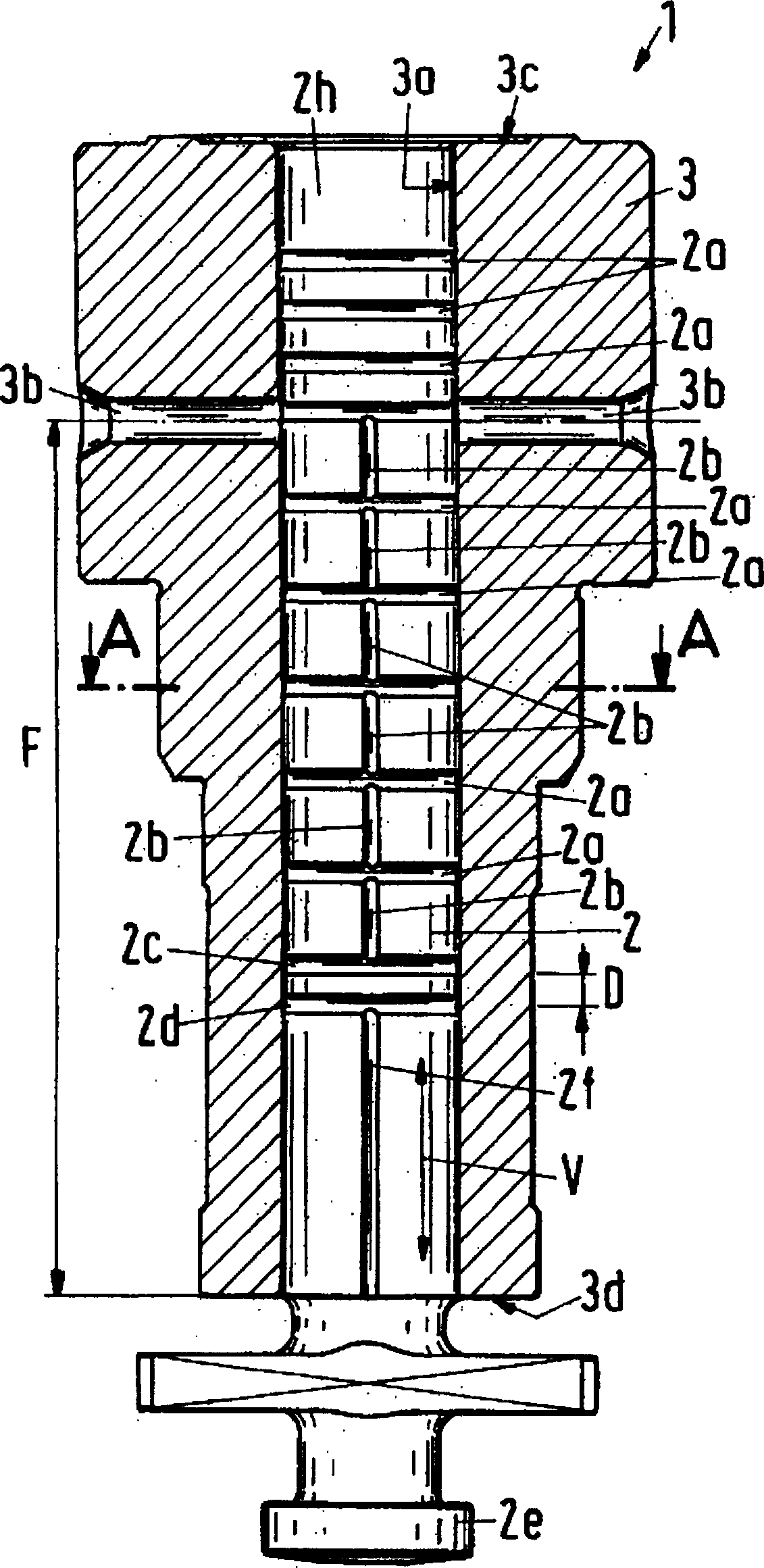
[0023] figure 1 A high-pressure piston-cylinder arrangement is shown, which comprises a cylinder 3 with a cylinder 3a and a piston 2 that is guided in the direction of movement V in the cylinder. Two fuel supply ports 3b open into the cylinder 3a. The piston 2 compresses the fuel flowing in through the fuel supply port 3b in the direction toward the high-pressure side 3c of the cylinder 3 . Atmospheric pressure preferably acts on the opposite cylinder 3 low-pressure side 3d.

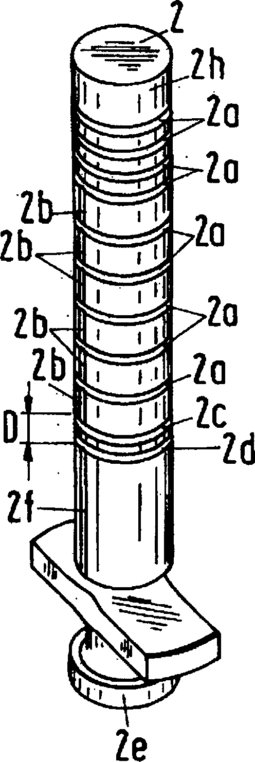
[0024] Such as figure 1 shown and see figure 2 The perspective view, the outer surface of the cylinder 3 has a first transverse groove 2c and a second transverse groove 2d, which are spaced apart from each other by a sealing length D. Such as figure 1 As shown, these transverse grooves 2c, 2d are arranged such that at any position of the piston reciprocating in the cylinder 3a, the transverse grooves are located between the fuel supply port 3b and the low pressure port 3d. The first transverse gro...


PUM


Abstract

A high-pressure piston-cylinder arrangement (1) for a high-pressure delivery pump of an internal combustion engine comprising a cylinder (3) with a cylinder barrel (3a) and a piston (2) guided in the direction of movement (V) in the cylinder barrel , the cylinder (3) has a fuel supply port (3b) leading into the cylinder barrel (3a), and the cylinder barrel (3a) has a section of inner cavity length (F) between the fuel supply port (3b) and the low pressure end (3d) , the piston (2) or the cylinder (3a) has at least first and second transverse grooves (2c, 2d) arranged at intervals in the moving direction (V), and it is characterized in that the first transverse groove (2c) is connected by a The channel (2b) is in flow communication with the fuel supply port (3b), and the second transverse groove (2d) is in flow communication with the low pressure end (3d) through another connecting channel (2f).

Description

technical field [0001] The invention relates to a high-pressure delivery pump for an internal combustion engine, in particular to a high-pressure piston-cylinder device. Background technique [0002] Patent publication WO 89 / 10479 discloses a high-pressure piston-cylinder arrangement suitable for use as a high-pressure pump such as a high-pressure delivery pump for a diesel engine. This high-pressure delivery pump is designed for injection pressures of at least 1000 bar. During the operation of such high-pressure delivery pumps, there is the risk that the piston will be bitten on the cylinder guide surface due to the high material load. [0003] A disadvantage of the known high-pressure delivery pumps is that the risk of piston seizure occurs at high pressures and / or high stroke frequencies. Contents of the invention [0004] The object of the invention is to create a high-pressure piston-cylinder arrangement in which the piston is not prone to jamming on the cylinder gu...

Claims


Application Information

Patent Timeline
Patent Type & Authority Patents(China)
IPC IPC(8): F02M59/44F02M59/00F02M59/26F02M63/00F04B53/08F04B53/14F04B53/18
CPCF02M59/44F02M63/0001
Inventor R·奥尔德
Owner WAERTSILAE SCHWEIZ AG
Learn More