Filling pump shaft

A technology of injecting polymer pump and shaft end, which is applied in the field of shaft structure and material improvement, and can solve the problems of waste of manpower and material resources, unsatisfactory effect of anti-corrosion and wear-resisting, and the surface of the shaft is susceptible to wear and corrosion.

Inactive Publication Date: 2006-10-18
于志伟
View PDF0 Cites 0 Cited by
  • Summary
  • Abstract
  • Description
  • Claims
  • Application Information

AI Technical Summary

Problems solved by technology

[0002] The shaft of the existing polymer injection pump is a metal and solid core structure. Since the working surface of the shaft is made of metal, the time is a little longer. The surface of the shaft is very easy to be worn and corroded when working in a liquid environment. This situation greatly affects the polymer injection pump. work efficiency and product quality
With the advancement of science and technology, although some anti-corrosion methods such as spraying or coating ceramic coatings on the surface of metal shafts are used, since only one layer of non-metallic or metallic materials is coated on the surface of metal shafts, this not only requires spraying The metal material cannot be too thick, and the connection between the non-metallic coating and the metal shaft is not firm, so the non-metallic coating is easily detached when the shaft is working, so the anti-corrosion and wear-resistant effects of this shaft are not Not ideal, some even have to replace the shaft once a month or so, which not only increases the labor intensity, but also increases the cost consumption, causes a lot of waste of manpower and material resources, and reduces the work efficiency

Method used


Image

  • Filling pump shaft

Examples


specific Embodiment approach 1

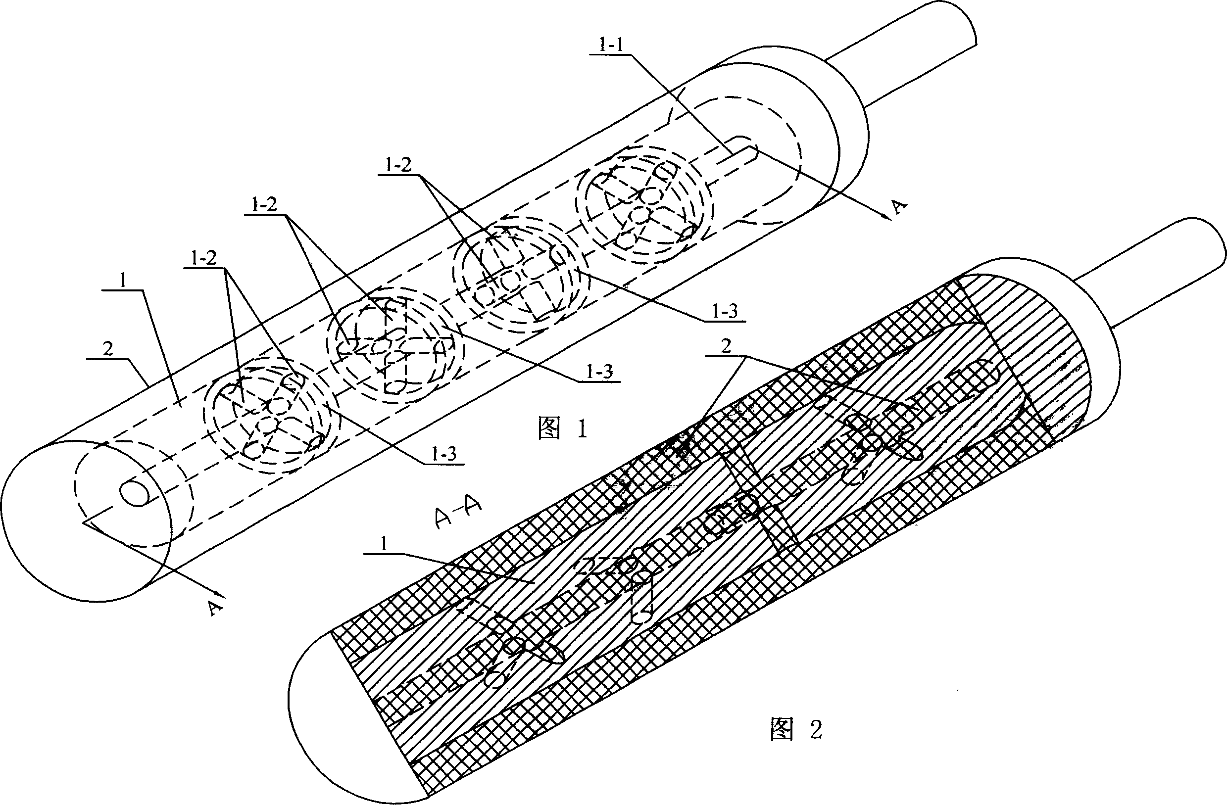
[0005] Embodiment 1: This embodiment includes a metal shaft core 1 and a non-metallic coating 2. The metal shaft core 1 has an axial hole 1-1 at the central axis, and the end of the axial hole 1-1 is opened on the metal shaft. The shaft end of the shaft core 1; a group of radial holes 1-2 are also arranged on the shaft core 1, and in the axial holes 1-1 and the radial holes 1-2 of the metal shaft core 1 and in the metal shaft core 1 The outer surface is injection molded with a non-metal material coating 2 .

specific Embodiment approach 2

[0006] Specific embodiment 2: In this embodiment, a group of radial holes 1-2 is opened on the shaft core 1, the number of radial holes 1-2 is eight, and the angle between two adjacent radial holes 1-2 is 120 degrees. Angle distribution, in the axial hole 1-1 and the radial hole 1-2 of the metal shaft core 1 and the outer surface of the metal shaft core 1, a non-metallic material coating 2 is injected, and the material of the non-metallic coating 2 is In PEEK, all the radial holes 1-2 intersect the axial holes 1-1 and are arranged at right angles.

specific Embodiment approach 3

[0007] Specific Embodiment Three: This embodiment is a preferred solution of the present invention: it includes a metal shaft core 1 and a non-metallic coating 2, and the metal shaft core 1 has an axial hole 1-1 at the central axis, and the axial The end of the hole 1-1 is opened on the shaft end of the metal shaft core 1; a groove 1-3 is opened on the outer surface circumference of the metal shaft core 1, and eight radial holes 1-2 are opened on the shaft core 1, The ends of the radial holes 1-2 are arranged in the groove 1-3, and the eight radial holes are divided into four groups, each group of two radial holes intersects at right angles, and all the radial holes 1-2 are connected to the shaft The intersecting holes 1-1 are set at right angles to the axial holes, and two adjacent radial holes 1-2 are distributed at an angle of 120 degrees, that is, one hole in a group of radial holes is connected to the adjacent group of radial holes. One hole in the radial holes is at an a...


PUM


Abstract

A polymer injection pump shaft relates to the improvement of a shaft structure and material. The shaft surface of the existing polymer injection pump is extremely susceptible to wear and corrosion, which greatly affects the working efficiency and product quality of the polymer injection pump. The metal shaft core (1) of the present invention has an axial hole (1-1) at the central axis, and the end of the axial hole (1-1) is opened at the shaft end of the metal shaft core (1); the shaft core ( 1) is also provided with a group of radial holes (1-2), in the axial hole (1-1) and radial hole (1-2) of the metal shaft core (1) and in the metal shaft core (1-2) ) is injection molded with a non-metallic material coating (2). The product of the present invention has strong mechanical strength and rigidity, fatigue resistance, wear resistance, radiation resistance, corrosion resistance, high and low temperature resistance, good self-lubricating and self-repairing properties, and low noise when working. The product of the present invention has broad The development prospect is conducive to popularization and application.

Description

Technical field: [0001] The invention relates to the improvement of a shaft (or plunger) structure and material. Background technique: [0002] The shaft of the existing polymer injection pump is a metal and solid core structure. Since the working surface of the shaft is made of metal, the time is a little longer. The surface of the shaft is very easy to be worn and corroded when working in a liquid environment. This situation greatly affects the polymer injection pump. work efficiency and product quality. With the advancement of science and technology, although some anti-corrosion methods such as spraying or coating ceramic coatings on the surface of metal shafts are used, since only one layer of non-metallic or metallic materials is coated on the surface of metal shafts, this not only requires spraying The metal material should not be too thick, and the connection between the non-metallic coating and the metal shaft is not firm, so the non-metallic coating is easily detac...

Claims


Application Information

Patent Timeline
Patent Type & Authority Patents(China)
IPC IPC(8): F04D29/04F04D7/00
Inventor 于志伟李法成
Owner 于志伟
Why Eureka
Try Eureka