Check patentability & draft patents in minutes with Patsnap Eureka AI!

Bidirectional drive orienting output wheel

A two-way drive, output wheel technology, applied in the direction of one-way clutches, clutches, mechanical equipment, etc., can solve the problem that the output wheel can only be driven forward in one direction, and achieve the effect of balanced movement and exercise, easy operation, and fatigue relief.

Inactive Publication Date: 2006-10-18
刘战国
View PDF0 Cites 4 Cited by
  • Summary
  • Abstract
  • Description
  • Claims
  • Application Information

AI Technical Summary

Problems solved by technology

Such as a bicycle flywheel, there is a shaft on the driving sprocket, and there are two pedals at both ends of the shaft. The shaft is installed in a fixed bushing on the frame and can rotate. The pawl sprocket is supported by the frame. The center of the rear wheel is connected to the drive sprocket through an endless chain. A ratchet mechanism, that is, a one-way clutch, is installed on the pawl sprocket to transmit the positive rotation force of the drive sprocket to the rear wheel shaft, that is, The user can sit on the seat and hold the handlebar with both hands, and then step on the pedal to rotate the drive sprocket in the forward direction, and the positive rotation force on the drive sprocket can be transmitted to the pawl sprocket through the chain, and thus is transmitted to the rear wheel, thereby turning the rear wheel and moving the bike forward on the ground, however, the detent sprocket's one-way clutch does not transfer the reverse rotational force on the drive sprocket when the drive sprocket rotates in reverse To the rear wheel, the pawl sprocket can only idle, that is, its output wheel can only be driven forward in one direction

Method used


Image

  • Bidirectional drive orienting output wheel
  • Bidirectional drive orienting output wheel
  • Bidirectional drive orienting output wheel

Examples


Embodiment Construction

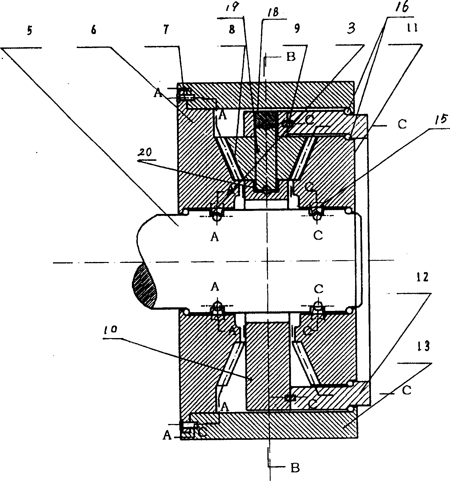
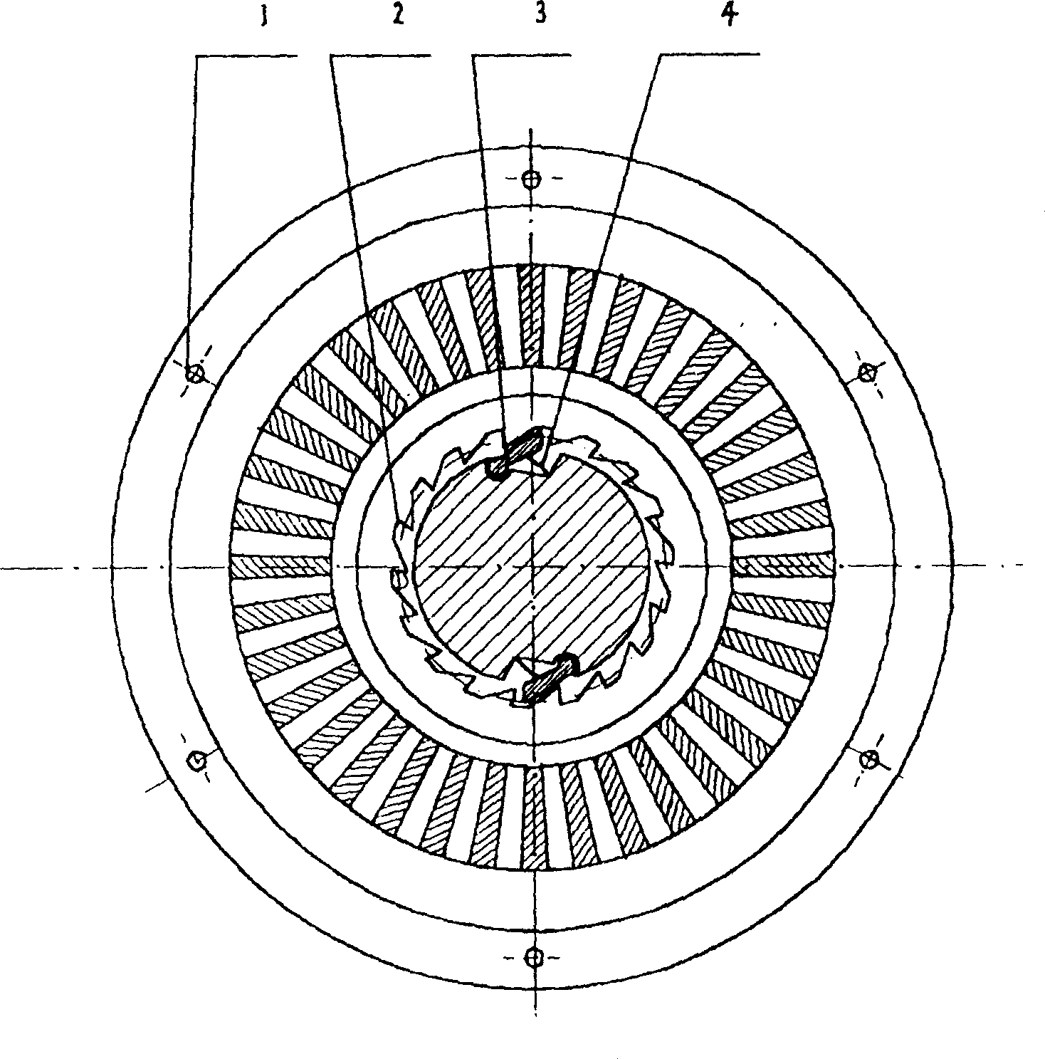
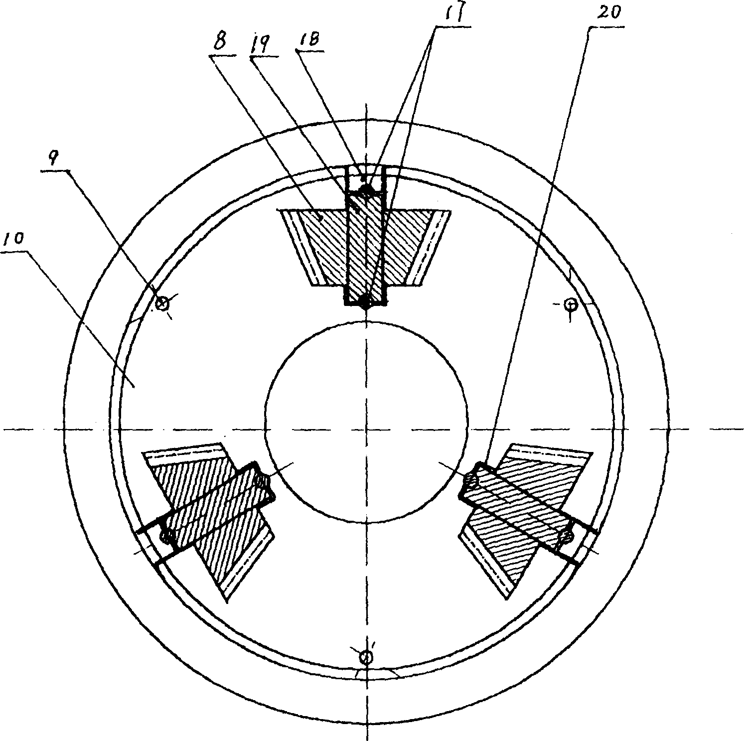
[0021] like Figure 1~4 As shown, the present invention consists of screw hole 1, first ratchet 2, first pawl 3, spring leaf 4, output shaft 5, first compound gear 6, bolt 7, bevel gear 8, fixed pin 9, disc 10 , the second composite gear 11, the fixed cylinder 12, the wheel body 13, the second ratchet 14, the second pawl 15, the ball bearing 16, the ball 17, the plunger 18, the rotating shaft 19 and the like. On the output shaft 5, the first compound gear 6 and the second compound gear 11 are oppositely arranged, and rolling bearings 16 are respectively installed between the output shaft 5 and the first and second compound gears 6, 11. One side of the first and second compound gears 6, 11 Conical teeth are respectively provided, and the tooth surfaces are opposite to each other. First and second ratchets 2 and 14 are provided on the inner walls of the first and second compound gears 6 and 11 respectively. 15 grooves, the spring leaf 4 supporting the ratchet is housed in the g...


PUM


Abstract

The invention relates to two-way drive technology, in particular to a two-way drive directional output wheel, which has an output shaft, a ratchet mechanism, and a wheel body, and a first compound gear (6) and a second compound gear (11) are relatively arranged on the output shaft (5) One side of the first and second compound gears (6, 11) is respectively provided with conical teeth, the tooth surfaces are opposite, and its inner wall is respectively matched with the output shaft (5) through a symmetrical ratchet mechanism, and the first and second compound gears (6, 11) 11) Conical gears (8) are installed between them, and the bevel gears (8) mesh with the first and second composite gears (6, 11) respectively, and one end of the wheel body (13) coaxial with the output shaft (5) is connected to the first A composite gear (6) is connected, and a fixed cylinder (12) is installed between the inner wall of the other end and the outer edge of the second composite gear (11), which are rolling fits with each other. The invention can realize that the output end of the upper-level device will rotate in a fixed direction when it is driven in two directions, forward or reverse, and has wide application in various mechanical equipment.

Description

technical field [0001] The invention relates to bidirectional drive technology, in particular to a bidirectional drive directional output wheel. Background technique [0002] In the known transmission mechanism of the wheel train, when the driving direction is reversed, the moving direction of the output end is also reversed, or the output end cannot be driven to move. Such as a bicycle flywheel, there is a shaft on the driving sprocket, and there are two pedals at both ends of the shaft. The shaft is installed in a fixed bushing on the frame and can rotate. The pawl sprocket is supported by the frame. The center of the rear wheel is connected to the drive sprocket through an endless chain. A ratchet mechanism, that is, a one-way clutch, is installed on the pawl sprocket to transmit the positive rotation force of the drive sprocket to the rear wheel shaft, that is, The user can sit on the seat and hold the handlebar with both hands, and then step on the pedal to rotate the ...

Claims


Application Information

Patent Timeline
Patent Type & Authority Patents(China)
IPC IPC(8): F16D41/18
Inventor 刘战国
Owner 刘战国
Features
  • R&D
  • Intellectual Property
  • Life Sciences
  • Materials
  • Tech Scout
  • Unparalleled Data Quality
  • Higher Quality Content
  • 60% Fewer Hallucinations
Learn More