Integrated light path switching type telescope with photographic function

An optical path switching and telescope technology, which is applied in the field of digital imaging, can solve the problems of fixed focal length, the field of view of the telescope cannot be completely matched, and is inconvenient to use, and achieves the effect of convenient conversion.

Inactive Publication Date: 2006-11-29
CHONGQING UNIV +1
View PDF2 Cites 0 Cited by
  • Summary
  • Abstract
  • Description
  • Claims
  • Application Information

AI Technical Summary

Problems solved by technology

However, since the optical paths of the two telescopes and the digital camera are completely independent, there are problems in this structure that the field of view of the telescope and the field of view of the digital camera cannot be completely matched, and the parallelism of the optical axes is difficult to guarantee, and it is impossible to realize "what you see is what you shoot". It brings a lot of inconvenience to the use; in addition, the focal length of the digital imaging part of the structure is fixed, which also brings certain limitations to the use

Method used


Image

  • Integrated light path switching type telescope with photographic function
  • Integrated light path switching type telescope with photographic function
  • Integrated light path switching type telescope with photographic function

Examples


Embodiment 1

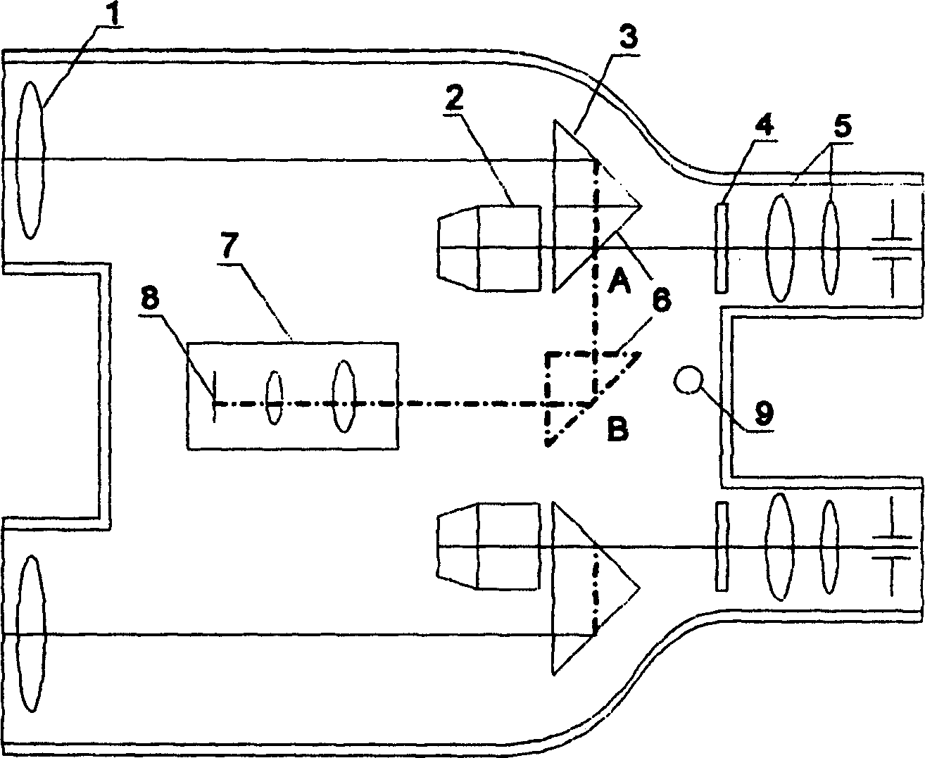
[0025] Embodiment 1: see figure 1 , figure 2 , Fig. 3, this integrated optical path switching type telescope with camera function is made of telescope and electrophotographic device, telescope is made up of two lens barrels left and right, electrophotographic device 7 is arranged between the two lens barrels, and the light-receiving surface of its sensor 8 Parfocal with eyepiece 5 of the telescope. An objective lens 1, an erecting device, a reticle 4 and an eyepiece 5 are sequentially arranged in the optical path of the telescope. Wherein the erecting device is made up of the second fixed rectangular prism 2, the first fixed rectangular prism 3 and the movable rectangular prism 6, and the rectangular faces of the first fixed rectangular prism 3 and the movable rectangular prism 6 are connected to form a combined right angle The prism, the combined right-angle prism and the second fixed right-angle prism 2 intersect each other at 90° to form a Paul prism erecting device. Th...

Embodiment 2

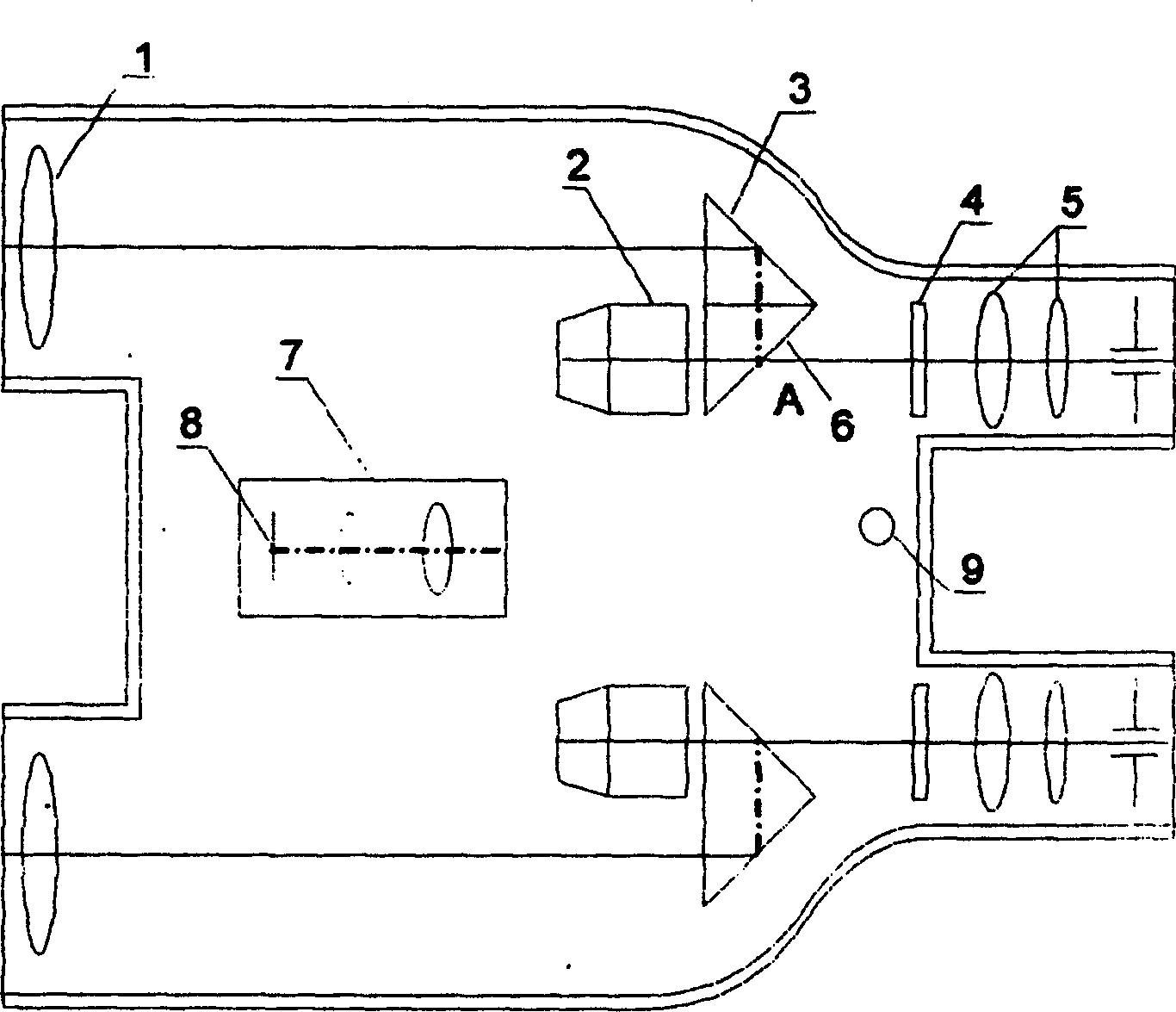
[0026] Example 2: see Figure 4 , in above-mentioned embodiment 1, movable rectangular prism 6 doubles as the reflector in the electrophotographic optical path, in the present embodiment, the moving position of movable rectangular prism 6 changes, moves from A to C place along optical axis, The reflected light of the first fixed right-angle prism 3 is not blocked, and another right-angle prism 12 is set at the intersection of the optical path of the electrophotographic device and the reflected light to reflect light into the optical path of the electrophotographic device to realize switching of the optical path.

Embodiment 3

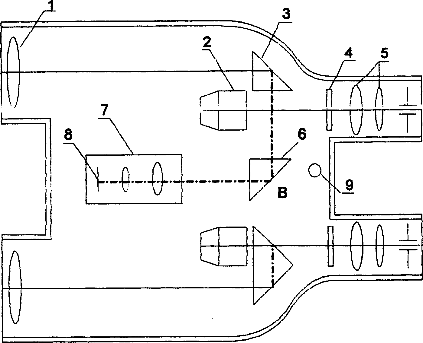
[0027] Embodiment 3: see Figure 5 , this embodiment is on the basis of example 2, and the rectangular prism 12 on the optical path of the electrophotographic device is replaced with a flat reflector 13, which is arranged at 90° with the fixed rectangular prism reflective surface. Simultaneously, the position switching mechanism adopts the form of toggle switch 10 .


PUM


Abstract

The prsent invention relates to an integrated optical circuit switched telescope with photographic function. The electronic photographic device is placed in the middle of binocular telescope, the telescope adopts Paul prism erecting device, and is formed from fixed right angle prism, mobile right angle prism and another fixed right angle prism. The mobile right angle prism is connected with position change-over mechanism and is driven by it, moved to near vacant position and separated from telescopic optical circuit. A reflecting device is placed in the front of electronic photographic device, and is opposite to the right angle face of the fixed right angle prism, so that the light of the telescopic optical circuit can be switched to the optical circuit of lectronic photographic device, and the light-receiving face of the sensor ofthe electronic photographic device is parafocal with telescopic eyepiece.

Description

[0001] Field: [0002] The invention belongs to the technical field of digital images, and in particular relates to an integrated optical path switching telescope with a camera function. Background technique: [0003] The telescope with photographic function is an organic combination of telescope and electronic photographic device. It realizes people's desire to take pictures while observing from a long distance, and its design concept has been widely praised. But for existing telescopes with photographic functions, it is only a simple combination of telescopes and electrophotographic devices. A telephoto camera introduced in Chinese patent 02236922.8 consists of a one-piece monocular telescope and a detachable Composed of a digital camera, the functions of telephoto and shooting can be realized. A kind of digital photographic telescope introduced in Chinese patent 02250520.2 is made up of a binoculars, an optical magnifying lens group and a digital photographic device, and c...

Claims


Application Information

Patent Timeline
Patent Type & Authority Patents(China)
IPC IPC(8): G02B23/00G02B23/12H04N5/225
Inventor 陈伟民岑军波黄尚廉
Owner CHONGQING UNIV
Why Eureka
Try Eureka