Eureka AIR delivers breakthrough ideas for toughest innovation challenges, trusted by R&D personnel around the world.

Tumor chemotherapy medicine preparation combiner

Pending Publication Date: 2022-02-08
SHAOYANG UNIV
View PDF10 Cites 0 Cited by
  • Summary
  • Abstract
  • Description
  • Claims
  • Application Information

AI Technical Summary

Problems solved by technology

[0003] In the prior art, medical personnel are required to manually dispense the medicine. At present, during the dispensing process, the medical personnel need to manually open the ampoule bottle and then draw the liquid medicine through the syringe for dispensing. During this process, the hands are easily contaminated by the liquid medicine. , and sometimes even opening the bottle will break the skin so that the liquid directly enters the blood and causes more serious damage. Therefore, a tumor chemotherapy drug preparation combiner is provided

Method used


Image

  • Tumor chemotherapy medicine preparation combiner
  • Tumor chemotherapy medicine preparation combiner
  • Tumor chemotherapy medicine preparation combiner

Examples


Embodiment 1

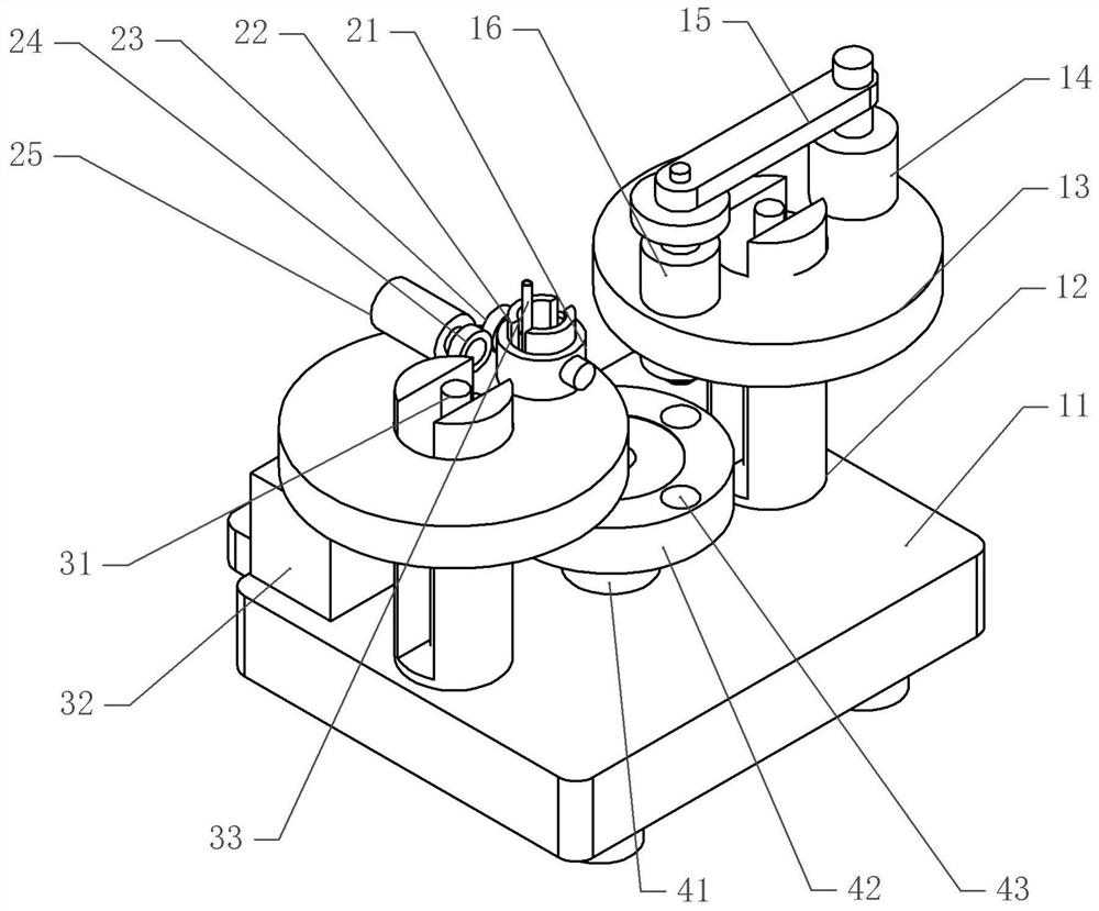
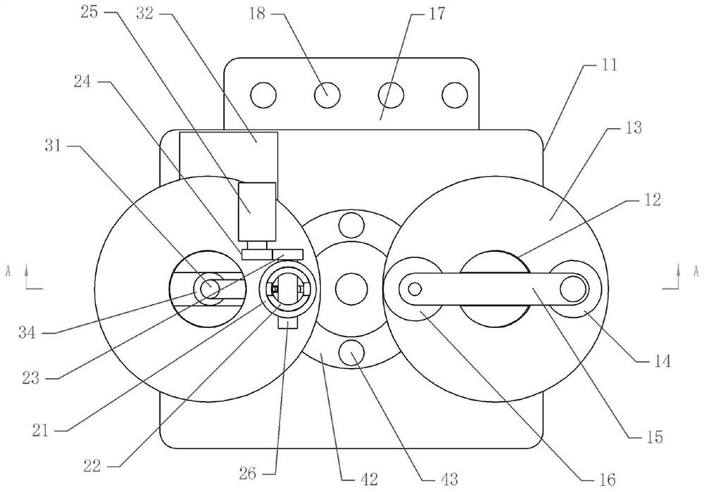
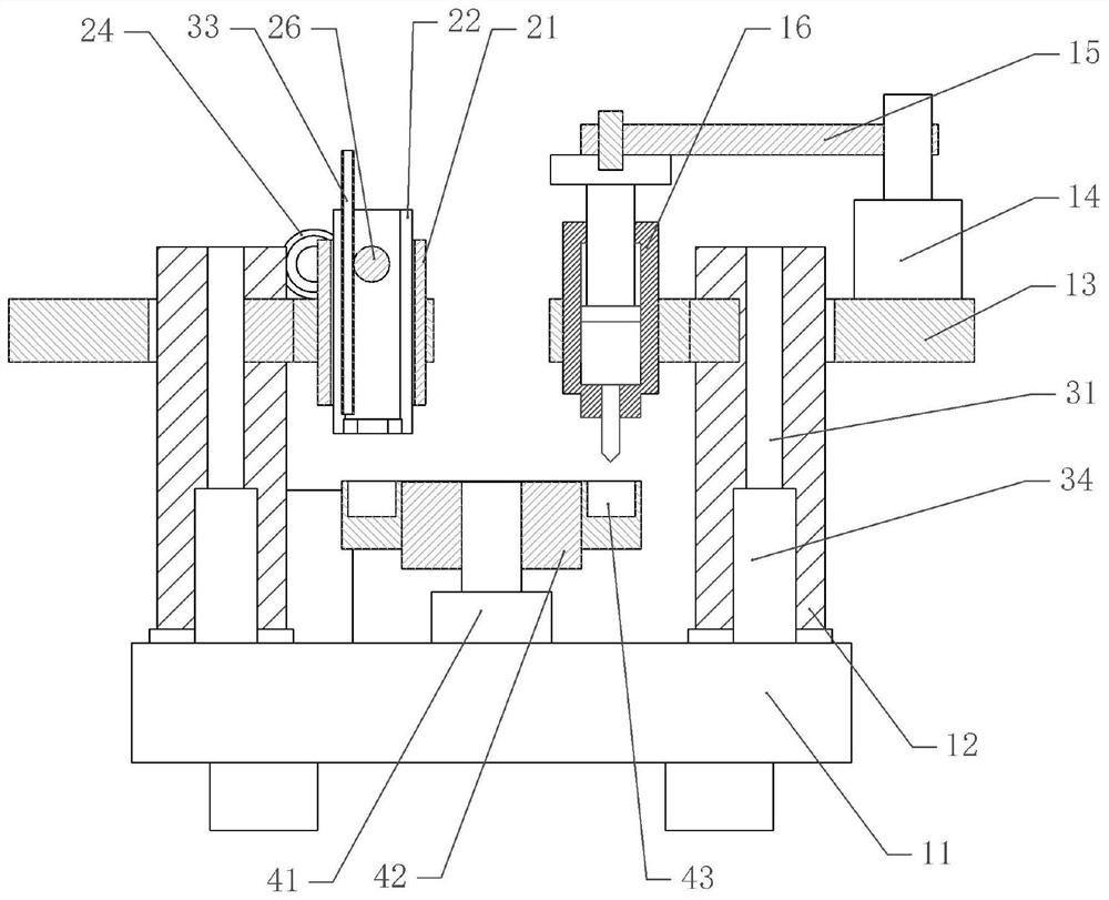
[0038] A tumor chemotherapeutic drug preparation combiner, as attached figure 1 , attached figure 2 And attached image 3 , comprising a support base 11, the support base 11 is horizontally slidably connected with a placement plate 17, and the placement plate 17 is provided with a plurality of placement grooves 18, the placement plate 17 and the placement grooves 18 can be used to place ampoules containing tumor chemotherapy drug preparations.

[0039] In the present embodiment, the bolts on the support base 11 are fixed with intermittently working driving parts, the driving parts are stepping motors 41, and the output shaft of the stepping motors 41 is coaxially fixed with a station plate 42, and the opening on the station board 42 is There are a number of station slots 43 for placing ampoules. A rubber layer is fixed in the station slots 43. The elastic deformation of the rubber layer can clamp ampules of different diameters, so that the ampoules are stably installed in th...

Embodiment 2

[0049] The difference between embodiment two and embodiment one is that, as attached Figure 4 As shown, in this embodiment, a controller and a displacement sensor installed on the right support plate 13 are also included. The displacement sensor is used to obtain the displacement information of the connecting plate 15 , and the controller is electrically connected to the electric control cylinder 14 . The controller is electrically connected with a distance sensor, and the distance sensor is installed on the crushing plate 22 . In this embodiment, the controller is electrically connected to the stepper motor 41 , the second motor 25 and the negative pressure pump.

[0050] The specific implementation process is as follows:

[0051] When the medical personnel input the starting signal to the controller, the controller controls the stepping motor 41 to work, and the stepping motor 41 works for 2s and at this time, the stepping motor 41 drives an ampoule on the station plate 42...


PUM


Abstract

The invention belongs to the technical field of medical equipment, and provides a tumor chemotherapy medicine preparation combiner. The combiner comprises a supporting seat, an intermittent working driving part is installed on the supporting seat, a station plate is fixed to the output shaft of the driving part, and a plurality of station grooves are formed in the station plate; conveying parts are fixed to the two sides of the station plate, a needle cylinder is detachably connected to the conveying part on one side and driven by a power part, and a crushing structure is arranged on the conveying part on the other side; and the crushing structure comprises a crushing barrel and a rotating shaft rotationally connected to the crushing barrel, the rotating shaft is connected with a driving assembly, the two sides of the rotating shaft are in threaded connection with crushing plates located in the crushing barrel, and the movement directions of the crushing plates are opposite. The combiner is simple in structure; and an ampoule bottle is crushed through the crushing structure, and then the power part is used for driving the needle cylinder to suck a liquid medicine in the ampoule bottle, so contact between operators and the liquid medicine is reduced.

Description

technical field [0001] The invention belongs to the technical field of medical equipment, and in particular relates to a tumor chemotherapy drug preparation combiner. Background technique [0002] In the process of tumor treatment, chemotherapy is a common treatment method, but the drugs required for chemotherapy are extremely toxic and will cause great damage to the healthy human body, but the use of chemotherapy drugs is mostly several or even multiple drugs Prepared in proportion. [0003] In the prior art, medical personnel are required to manually dispense the medicine. At present, during the dispensing process, the medical personnel need to manually open the ampoule bottle and then draw the liquid medicine through the syringe for dispensing. During this process, the hands are easily contaminated by the liquid medicine. , Even sometimes opening the bottle will break the skin so that the medicinal liquid directly enters the blood and causes more serious damage. Therefor...

Claims


Application Information

Patent Timeline
Patent Type & Authority Applications(China)
IPC IPC(8): B02C19/00B02C23/00B02C25/00B08B5/04B08B15/04A61J1/20B67B7/92
CPCB02C19/0087B02C23/00B02C25/00B08B5/04B08B15/04A61J1/2003A61J1/2051A61J1/2096B67B7/92
Inventor 李勇杰封芬马红玉欧阳恩鸿魏海谅
Owner SHAOYANG UNIV
Why Eureka
Eureka Blog
Learn More