Air flowing transversely type drum dryer

A drum dryer and cross-flow technology, which is applied in household dryers, washing devices, textiles and papermaking, etc., can solve the problems of general products without structure

Inactive Publication Date: 2006-12-13
LG ELECTRONICS (TIANJIN) APPLIANCES CO LTD
View PDF0 Cites 1 Cited by
  • Summary
  • Abstract
  • Description
  • Claims
  • Application Information

AI Technical Summary

Problems solved by technology

[0012] In order to solve the above-mentioned problems of tumble dryers, relevant manufacturers have tried their best to find a solution, but no suitable design has been developed for a

Method used


Image

  • Air flowing transversely type drum dryer
  • Air flowing transversely type drum dryer
  • Air flowing transversely type drum dryer

Examples


Example Embodiment

[0059] The specific implementation, structure, features and effects of the cross-flow tumble dryer according to the present invention will be described in detail below with reference to the accompanying drawings and preferred embodiments.

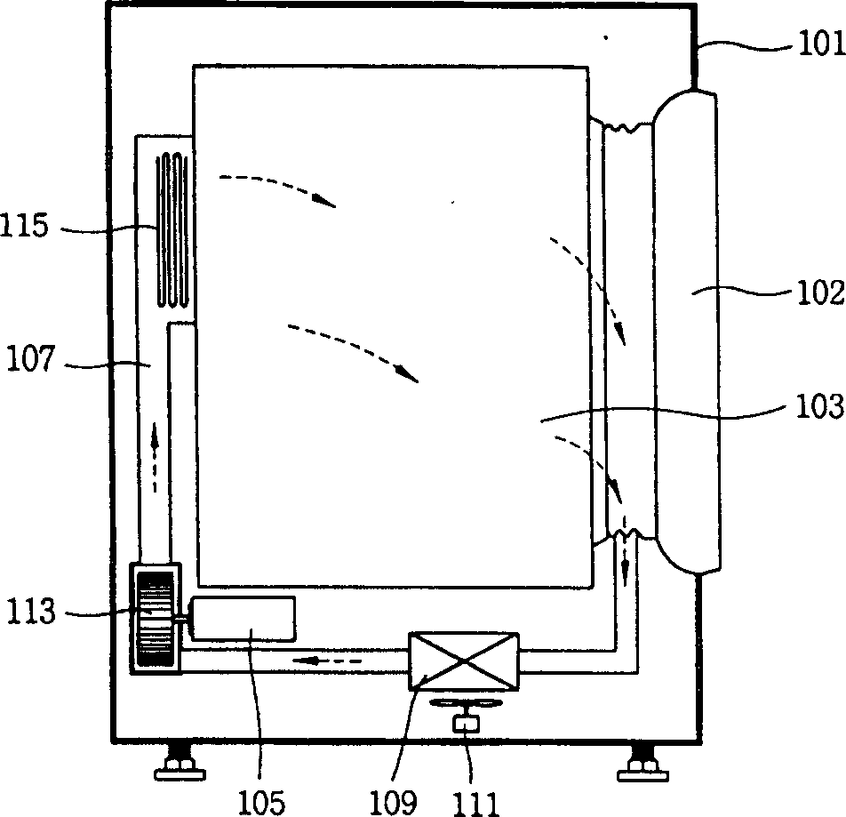
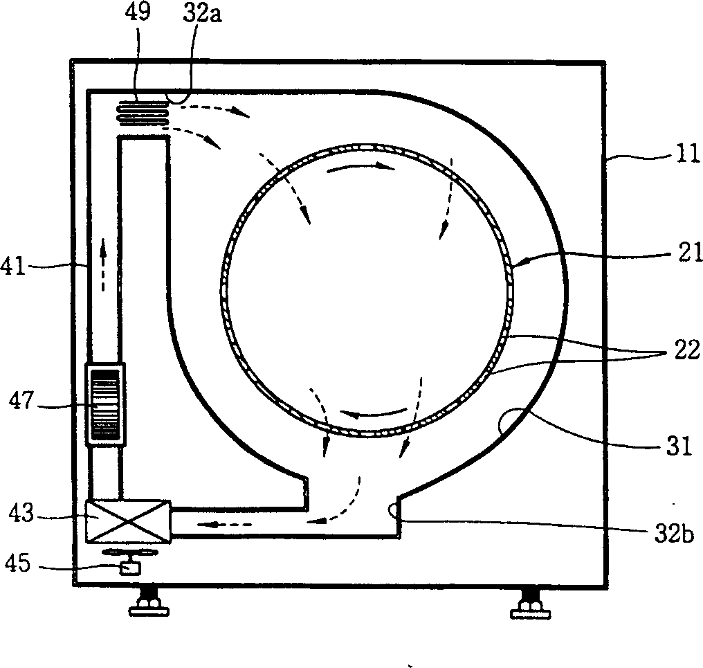
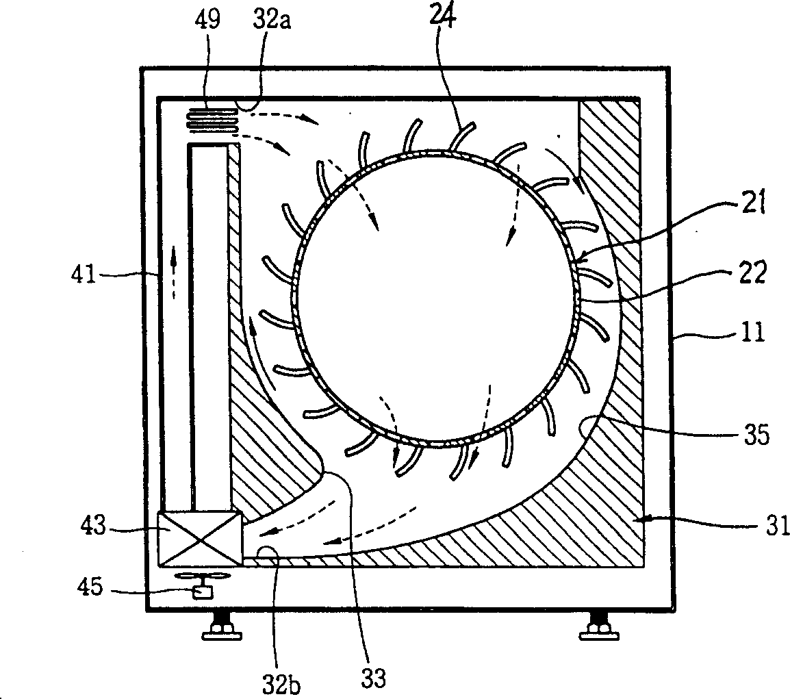
[0060] see figure 2 Shown is a schematic longitudinal cross-sectional view of the first embodiment of the cross-flow tumble dryer of the present invention. The cross-flow tumble dryer of the present invention mainly includes the following components: a casing 11 with an accommodation space is formed inside; a plurality of ventilation openings are provided, so that the air can flow laterally relative to the axial direction on the circumferential surface, and the casing 11 is formed in the casing 11. A rotating drum 21, which is arranged in a substantially horizontal direction and can be rotated around the rotating shaft, is installed inside 11; around the rotating drum 21; The outflow side of 31 communicates with each other, and the other ...


PUM


Abstract

The transversely flowing cylindrical stoving machine has the structure including casing to form inside holding space; rotating cylinder for holding clothing to be dried, capable of rotating horizontally and with ventilating ports set for air to flow transversely; air flow channel set inside the casing for air to flow axially and transversely around the rotating cylinder; and blower to ensure air flow along the air flow channel. By means of the said structure, air can flow transversely in axial direction of the cylinder to raise the stoving effect.

Description

technical field [0001] The invention relates to a drum dryer in heating and ventilation equipment in the field of mechanical engineering, in particular to a cross-flow drum dryer which can make air flow laterally in the axial direction of the rotating drum and improve the drying function ( CROSS FLOW TYPE DRUM DRYING MACHINE). Background technique [0002] Existing tumble dryers are equipped with a roughly horizontal rotating drum inside the casing, and inject high-temperature dry air into the rotating drum to absorb the moisture of the dried object, and then discharge it to the outside of the rotating drum. It is one of the dryers to complete the drying function of the dried object. [0003] This dryer has an exhaust type dryer that absorbs moisture from the rotating drum and discharges the air to the outside of the cabinet, and a dryer that condenses the air discharged from the rotating drum and removes moisture, and re-injects the air into the rotating drum after heating...

Claims


Application Information

Patent Timeline
IPC IPC(8): D06F58/02
Inventor 朴永焕洪京燮郑春勉
Owner LG ELECTRONICS (TIANJIN) APPLIANCES CO LTD
Why Eureka
Try Eureka