Through hole for reflection type LCD

A liquid crystal display, reflective technology, used in static indicators, instruments, optics, etc., to solve problems such as incomplete grinding, light leakage in dark states, and poor alignment

Inactive Publication Date: 2007-01-03
AU OPTRONICS CORP
View PDF4 Cites 0 Cited by
  • Summary
  • Abstract
  • Description
  • Claims
  • Application Information

AI Technical Summary

Problems solved by technology

When the display is aligned, the corners of the through holes 214 opposite to the brushing direction will be incompletely brushed, resulting in a dead area 214a, resulting in poor alignment and light leakage in the dark state

Method used


Image

  • Through hole for reflection type LCD
  • Through hole for reflection type LCD
  • Through hole for reflection type LCD

Examples


Embodiment Construction

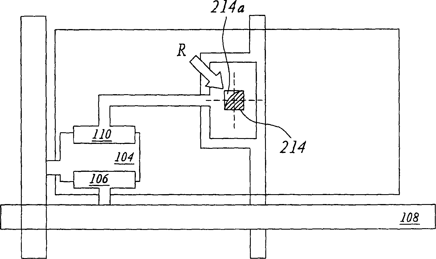
[0030] Such as figure 2 As shown in the traditional square through hole in , relative to the corner 214a of the brushing direction, there will be a dead angle that cannot be brushed. For this, the present invention utilizes the method of changing the shape and profile of the through hole to improve the situation of dark state light leakage caused by misalignment.

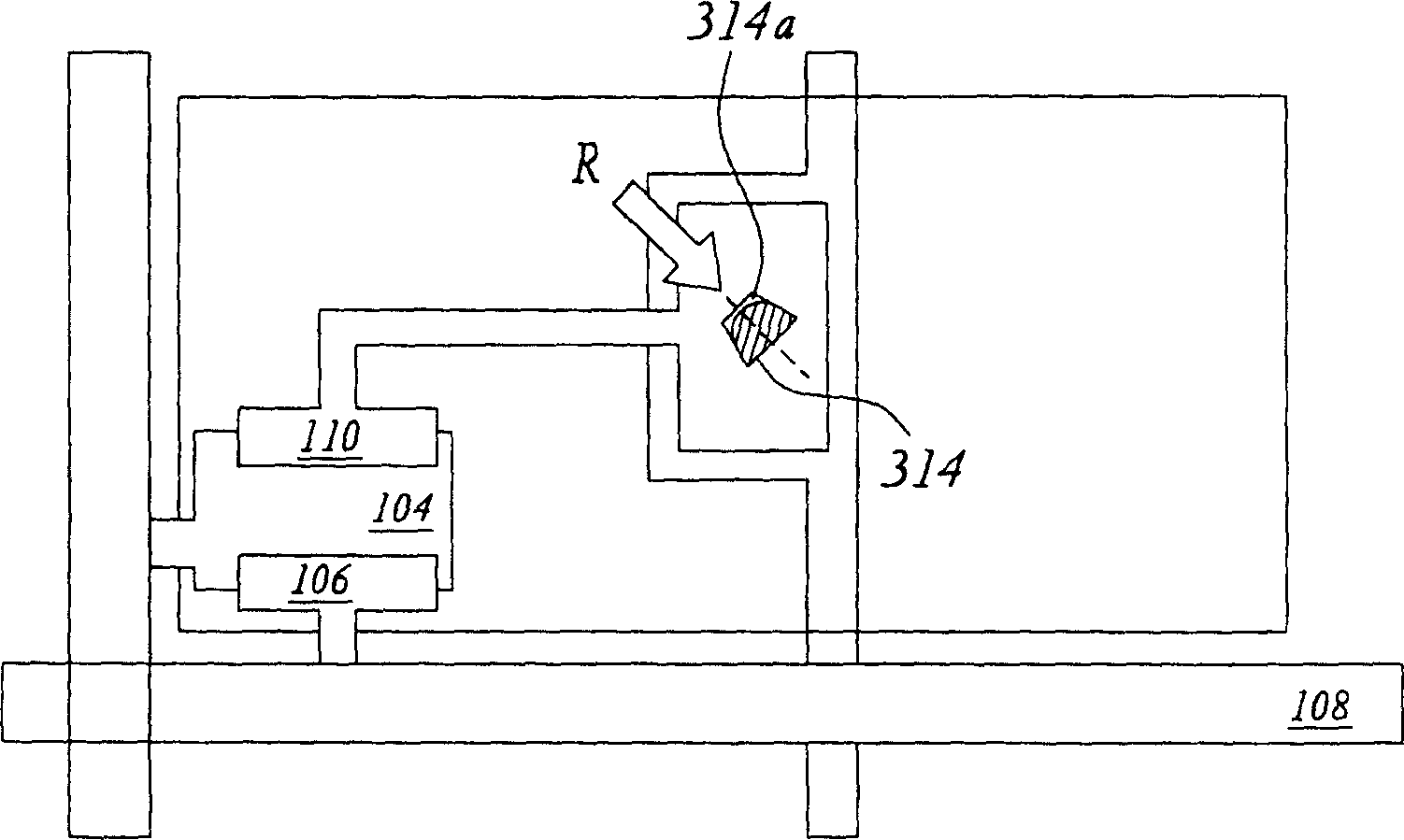
[0031] Please refer to image 3 , which shows a schematic top view of the through hole according to the first embodiment of the present invention. image 3 Among them, the end of the through hole 314 relative to the source direction R of the brush movement is reduced, and the shape is also changed from a square to a trapezoid, that is, the short side of the trapezoid is relative to the direction of the matching movement source. In addition, it is more preferable to rotate the through hole 314 so that its central axis of symmetry is parallel to the brushing direction R. As shown in FIG. According to the experimen...


PUM


Abstract

The invention discloses a reflecting LCD through hole, used to connect a drain with a pixel electrode. Its shape is corresponding to LCD phase feeding direction and its symmetrical central axis is parallel to the phase feeding direction. Where, one end of it corresponding to the phase feeding direction is less than the other end in shape, so as to improve dark-state light leak caused by bad phase feeding direction and then effectively heighten the reflecting LCD contrast.

Description

technical field [0001] The invention relates to a through hole for connecting a drain electrode and a pixel electrode in a reflective liquid crystal display, in particular to an opening shape of the through hole to improve light leakage in a dark state caused by poor alignment. Background technique [0002] The development of imaging technology is changing with each passing day. Taking the display as an example, the traditional cathode ray tube display has gradually faded out of the high-end display market in recent years due to its large size and severe radiation. (Liquid Crystal Display, LCD). The liquid crystal display can be divided into reflective liquid crystal display and transmissive liquid crystal display according to the optical technology. [0003] figure 1 A cross-sectional view of a reflective thin film transistor liquid crystal display is shown. A reflective type active matrix (AM)-LCD 100 is composed of a plurality of pixels arranged in a matrix. Each pix...

Claims


Application Information

Patent Timeline
Patent Type & Authority Patents(China)
IPC IPC(8): G02F1/133G02F1/136G09F9/35
Inventor 陈伯纶
Owner AU OPTRONICS CORP
Why Eureka
Try Eureka