Solid bowl helical conveyor centrifuge with a pressurized housing

A technology of screw conveying and non-porous drum, applied in centrifuges with rotating drums, centrifuges, etc., can solve the problems of increasing driving power, increasing power consumption of centrifuges, heating of gas and rotating parts, etc. The effect of preventing electric shock, lowering of cooling equipment, lowering of temperature rise

Inactive Publication Date: 2007-01-10
WESTFALIA SEPARATOR AG
View PDF5 Cites 0 Cited by
  • Summary
  • Abstract
  • Description
  • Claims
  • Application Information

AI Technical Summary

Problems solved by technology

[0004] The friction that occurs between the gas molecules and the drum surface, especially at high speeds and / or large diameter drums, requires considerable drive power, thus increasing the power consumption of the centrifuge to such an extent that it becomes a shortcoming of
Another problem is that these energy losses cause heating of the gas and rotating parts
Wall friction increases the pressure proportionally, which increases the drive power required

Method used


Image

  • Solid bowl helical conveyor centrifuge with a pressurized housing
  • Solid bowl helical conveyor centrifuge with a pressurized housing
  • Solid bowl helical conveyor centrifuge with a pressurized housing

Examples


Embodiment Construction

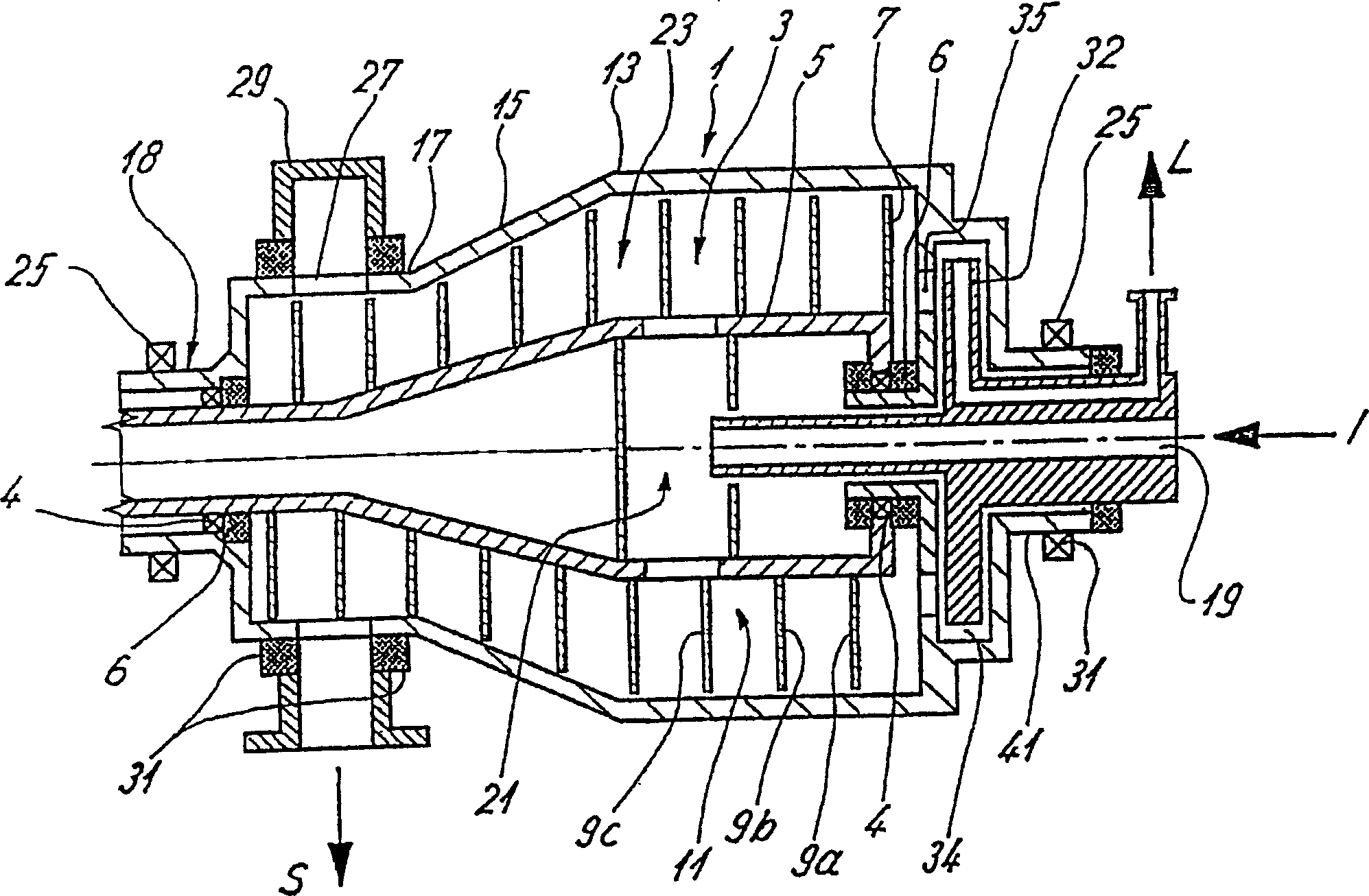
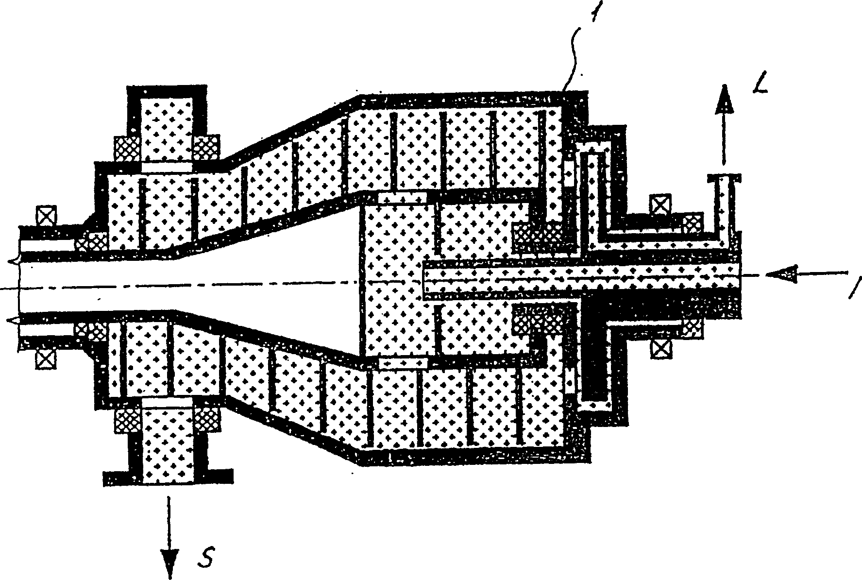
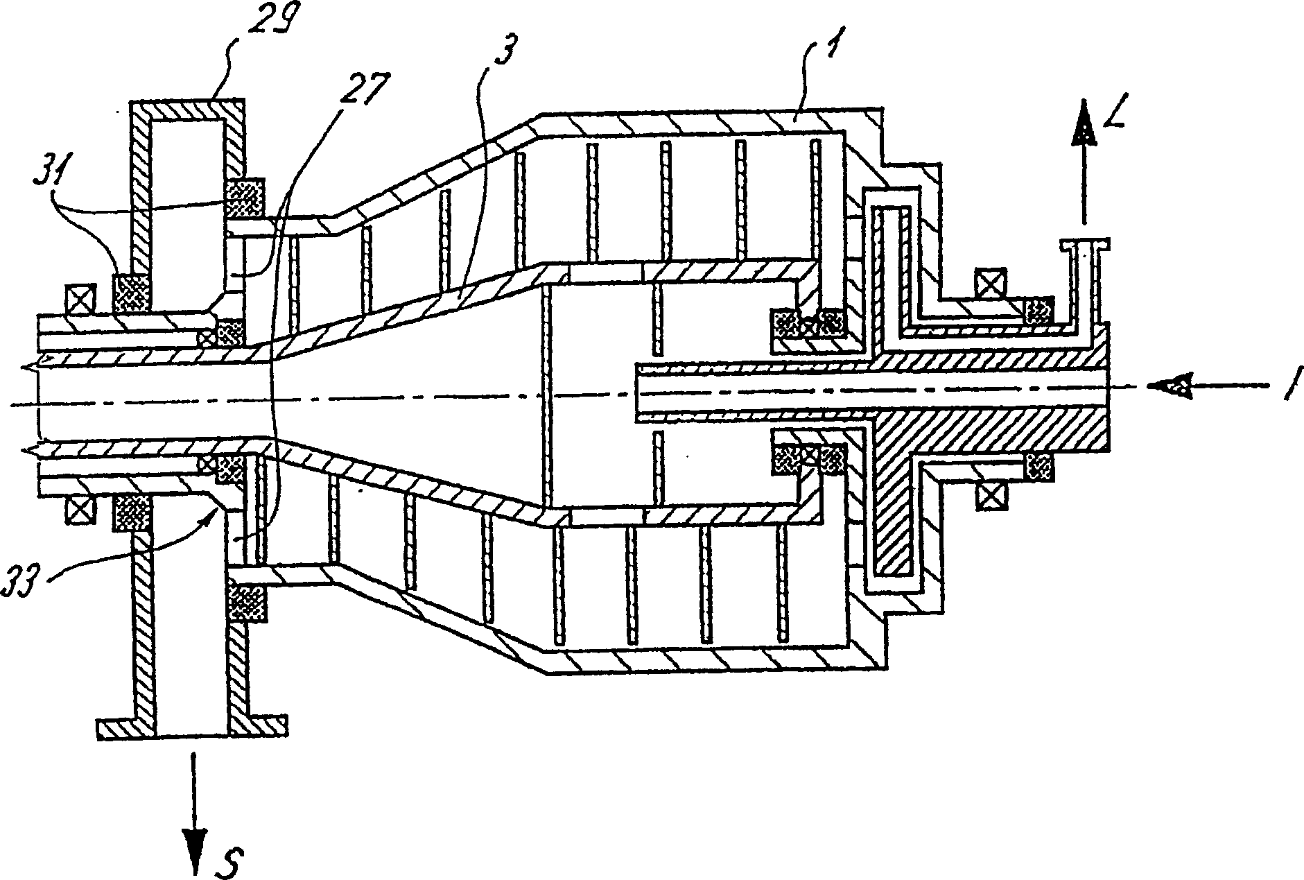
[0030] figure 1 Shown is a non-perforated drum screw conveying centrifuge with a drum 1 and a helical rotor 3 inside the drum 1 with a helical rotor body 5 and a helical plate wound on the body 5 in the form of a helix 7. The channel 11 for conveying the material to be centrifuged is located between the spirals 9a, 9b, . . . A bearing 4 and a sealing ring 6 are arranged between the drum 1 and the screw rotor body 5 at both ends of the non-porous drum screw conveying centrifuge.

[0031] exist figure 1 In the rear region, the centrifuge bowl has a cylindrical portion 13 and in its front region has a conical portion 15 adjacent to the cylindrical portion 13 (or graded). The drum also has a further cylindrical portion 17 axially adjoining the conical portion 15, to which a head 18 of the drum (and / or a hub) is connected.

[0032] The centrifuged material I enters the distributor 21 through the centrally arranged inlet pipe 19, and from there enters the centrifugal space 23 ...


PUM


Abstract

A solid bowl helical conveyor centrifuge. The centrifuge includes a rotating drum, having a centrifuge space with a screw that can also rotate. An inlet tube for supplying a material for centrifugation into the centrifuge space, and at least one liquid discharge and at least one solids discharge, wherein the liquid discharge and / or the solid discharge is / are designed as at least one or more openings in a rotating part of the solid bowl helical conveyor centrifuge, in particular through openings in the drum wall. At least one of the openings is covered by a housing which encloses the drum of the solid bowl helical conveyor centrifuge in only some sections, between the at least one housing and the drum and / or other rotating elements of the solid bowl helical conveyor centrifuge (drum heads, hubs) at least one or more gaskets are provided.

Description

technical field [0001] The invention relates to a non-porous drum screw-fed centrifuge comprising a pressure-tight drum comprising a centrifuge space in which is also rotatable a helical rotor; The centrifuge also includes an inlet pipe for feeding the material to be centrifuged into the centrifuge space. Background technique [0002] In order to ensure the pressure-tight and air-tight operation of the non-porous drum screw conveyor centrifuge, it is known that the entire drum (that is, the entire rotating area of ​​the drum) can be surrounded by a shell that is sealed from the surrounding environment. [0003] Inside this housing, the boundary states of the process to be realized can be maintained and the mass flow can be moved under the required pressure conditions. [0004] The friction that occurs between the gas molecules and the drum surface, especially at high speeds and / or large diameter drums, requires considerable drive power, thus increasing the power consumption...

Claims


Application Information

Patent Timeline
Patent Type & Authority Patents(China)
IPC IPC(8): B04B7/02B04B1/20B04B11/08B04B7/00
CPCB04B2001/2083B04B7/00B04B11/082B04B7/02B04B1/20
Inventor H·贝俄A·蒙肯布施M·雷齐恩巴赫M·穆勒
Owner WESTFALIA SEPARATOR AG
Why Eureka
Try Eureka