
Sealed device for drive-shaft

A technology of sealing device and transmission shaft, which is applied in the direction of propulsion transmission device, engine seal, transmission device with synchronous propulsion parts, etc. It can solve the problems of not knowing and not being able to align the transmission shaft well, and achieve optimal pressure discharge effect of effect

Inactive Publication Date: 2007-02-07
B+V工业技术股份有限公司
View PDF4 Cites 0 Cited by
  • Summary
  • Abstract
  • Description
  • Claims
  • Application Information

AI Technical Summary

Problems solved by technology

So far, no effective method of preventing this crevice corrosion is known
Also the inner bushing doesn't align well with the drive shaft underwater

Method used


Image

  • Sealed device for drive-shaft
  • Sealed device for drive-shaft
  • Sealed device for drive-shaft

Examples


Embodiment Construction

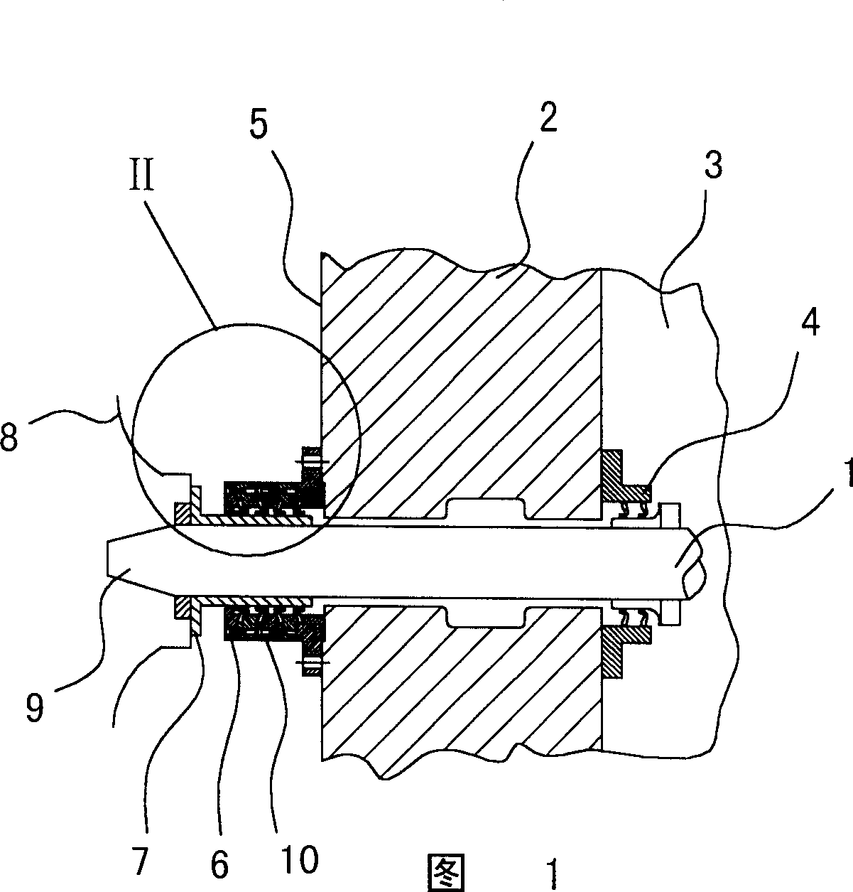
[0030] According to the embodiment shown in FIG. 1 , a drive shaft 1 passes through a ship's outer wall 2 . In the area of ​​a ship interior 3 , a clamping sleeve 4 guides the drive shaft 1 in a sealing manner. Arranged on the outer side 5 of the ship's outer wall 2 is an outer bushing 6 which is fixedly joined to the ship's outer wall.

[0031] An inner shaft sleeve 7 is enclosed within the outer shaft sleeve 6, and it is clamped on the propeller 8 of the ship. The inner shaft sleeve 7 is contained on the outer sector 9 of the transmission shaft 1, which passes through the outer wall 2 of the ship to its outside.

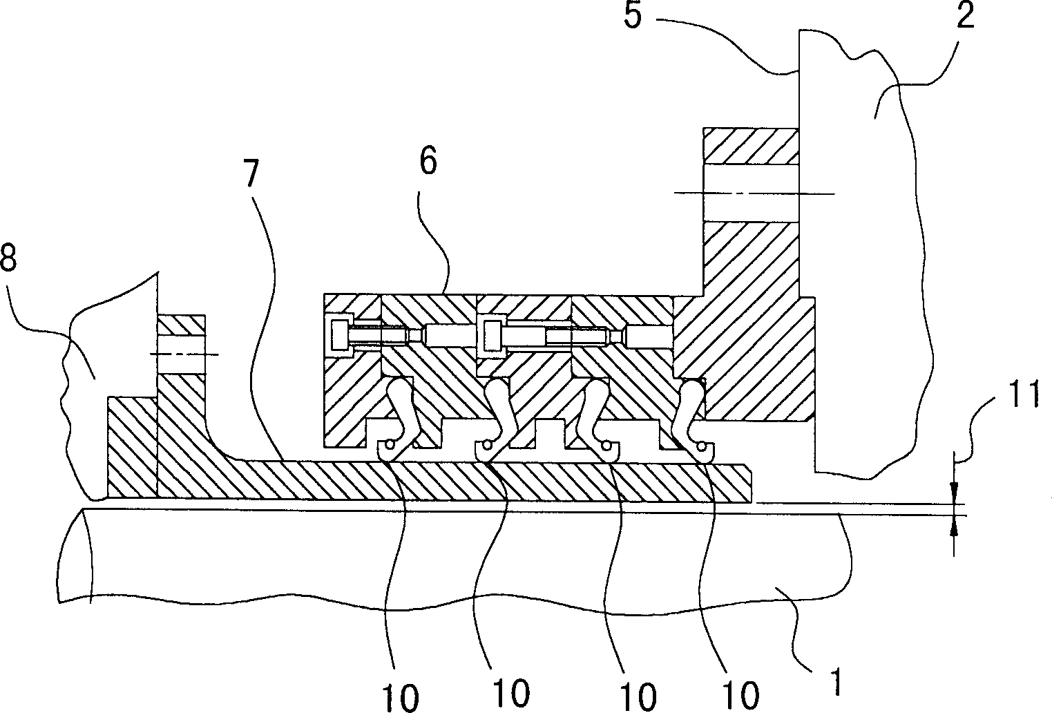
[0032] figure 2 It is an enlarged schematic diagram of various parts of the II part in Fig. 1 . It can be seen from the figure that the outer sleeve 6 clamps a plurality of sealing elements 10 which tightly press the inner sleeve 7 . In this way a good sealing effect is achieved between the inner bushing 7 which rotates with the transmission shaft 1 and the out...


PUM


Abstract

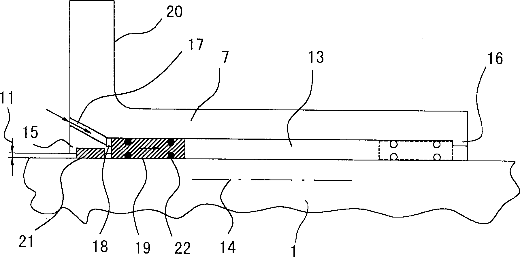
The sealing device has a inner bush guided on a propeller drive shafts for sealing the propeller drive shafts.The inner bush is guided in an outer bush and has an inside diameter that is greater than an outside diameter of the drive shaft to be guided. The inner bush has at least one oil or grease channel which is provided with at least one discharge opening in the vicinity of an inner side of the inner bush and can be connected to an oil or grease transport device.

Description

technical field [0001] The invention relates to a drive shaft seal, which has an inner sleeve which is placed on the drive shaft and which is guided into an outer sleeve. The inner sleeve has an inner diameter which is larger than the outer diameter of the guided drive shaft diameter size. Background technique [0002] Devices of this type are used to ensure adequate sealing in the area where the propeller shaft of a ship passes through the ship's wall. A typical implementation form is that the outer sleeve and the ship wall are fastened with bolts; the outer sleeve clamps annular sealing elements, and these sealing elements seal the gap between the outer sleeve and the inner sleeve, while the inner sleeve is opposite to each other. There is a possibility of movement in the outer shaft sleeve. The inner bushing has a flange that is fixed to the propeller of the boat. [0003] There is generally a narrow annular gap between the inner bushing and the drive shaft. Particula...

Claims


Application Information

Patent Timeline
IPC IPC(8): F16J15/46B63H23/36B63H23/32F16C3/02F16J15/00F16J15/10F16J15/16F16J15/18
CPCF16J15/004B63H23/321F16J15/162F16J15/18
Inventor E·-P·冯贝根
Owner B+V工业技术股份有限公司
Learn More