
Flying type evaporator

A technology for evaporators and evaporator fans, which is applied to evaporators/condensers, airflow control components, refrigeration components, etc., and can solve the problems of no air regulating plate at the outlet of the fan and the inability to adjust the direction

Inactive Publication Date: 2007-02-14
NAT ENG AN TECH RES CENT FOR PRESERVATION OF AGRI PROD TIANJIN
View PDF5 Cites 0 Cited by
  • Summary
  • Abstract
  • Description
  • Claims
  • Application Information

AI Technical Summary

Problems solved by technology

[0002] There is no air regulating plate at the outlet of the evaporator fan of an ordinary refrigerator, and the cold air blows in a fixed direction, and the direction cannot be adjusted to the place that needs cooling in the cold storage

Method used


Image

  • Flying type evaporator
  • Flying type evaporator
  • Flying type evaporator

Examples


Embodiment Construction

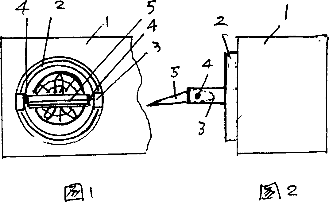
[0015] As shown in Figure 1, an evaporator is provided with a circular track groove 2 at the fan outlet of the refrigeration evaporator 1, and a movable support 3 is arranged on the circular track groove, and the two movable supports are connected by a shaft 4 to the wind direction flap 5 on both sides. The air-regulating vane arranged at the fan outlet is one piece. As shown in Figure 2, the cross section of the wind direction flap is the streamlined cross section of the aircraft wing.

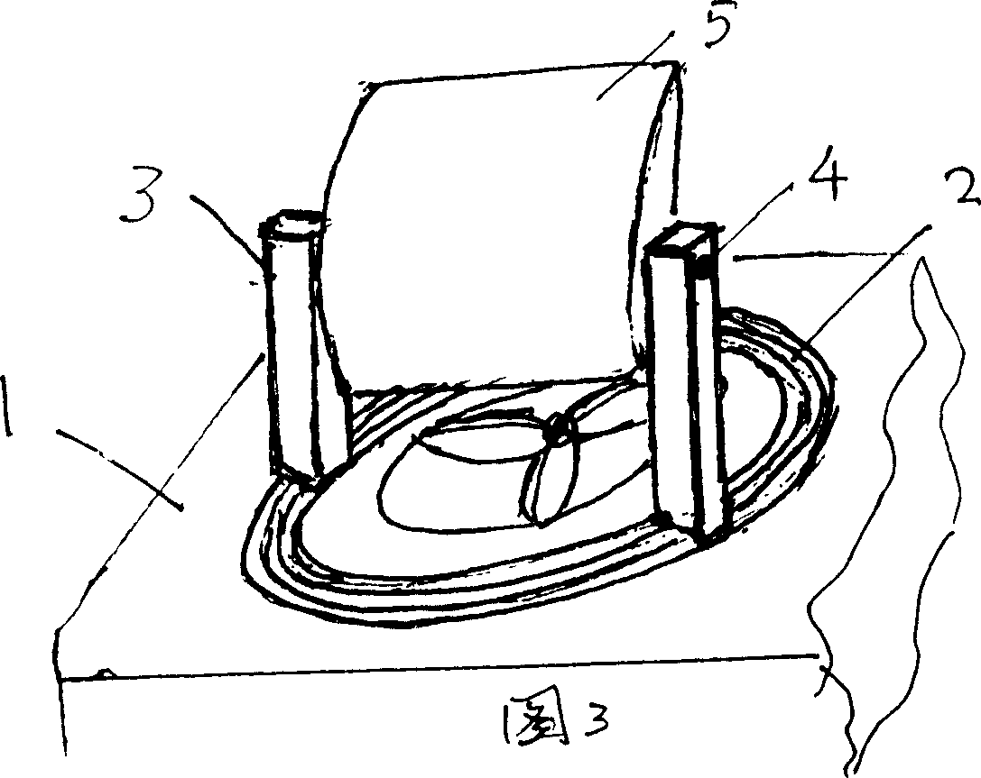
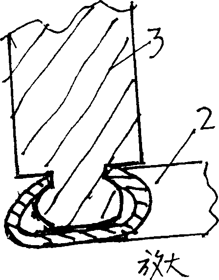
[0016] What Fig. 3 shows is the adjustable direction wing plate structure of the evaporator. The circular track groove 2 is provided with a movable support 3, and the two movable supports are connected by the shaft 4 to the two sides of the air regulating wing plate 5. Figure 4 It is the sectional structure of the movable support 3 and the circular track groove 2 of the evaporator. The movable support 3 can slide in the circular track groove, and the support can rotate 360 ​​degrees on the ...


PUM


Abstract

The present invention relates to a flying type evaporator. It is characterized by that at refrigeration evaporator fan mouth position a circular track groove is set, on the circular track groove the movable supporting frames are set, two movable supporting frames are connected with two sides of air direction regulating wing plate by means of shaft, and the section of said wing plate is streamlined section of aircraft aerofoil. The above-mentioned supporting frame can be rotated at 360 deg. on the circular track groove, and the air direction regulating wing plate also can be rotated on the supporting frame. Said invention can be used in cold storage warehouse for protecting fresh-keeping product.

Description

technical field [0001] The invention belongs to a refrigerator evaporator, in particular to an evaporator. Background technique [0002] There is no air regulating plate at the fan outlet of the evaporator of an ordinary refrigerator, and the cold air coming out blows in a fixed direction, and the direction cannot be adjusted to the place that needs cooling in the cold storage. Contents of the invention [0003] The technical problem to be solved by the present invention is to provide an evaporator, the cold air from the outlet of the fan of the evaporator of the refrigerator can be adjusted to the place where cooling is required in the cold storage. [0004] Technical scheme of the present invention is: [0005] An evaporator, characterized in that: a circular track groove is provided at the fan outlet of the refrigeration evaporator, and a movable support is provided on the circular track groove, and there are shafts on the two movable supports, and the shafts are conne...

Claims


Application Information

Patent Timeline
Patent Type & Authority Patents(China)
IPC IPC(8): F25B39/02F24F13/16
Inventor 李喜宏陈丽胡云峰关文强王莹
Owner NAT ENG AN TECH RES CENT FOR PRESERVATION OF AGRI PROD TIANJIN
Learn More