Box frame assembly

A box-shaped frame and frame technology, which is applied to display shelves, display hangers, building components, etc., can solve the problems of unattractive frames and increase manufacturing costs, reduce manufacturing costs and material costs, and simplify assembly and disassembly. Effect

Inactive Publication Date: 2007-02-28
SKYLINE DISPLAY
View PDF10 Cites 0 Cited by
  • Summary
  • Abstract
  • Description
  • Claims
  • Application Information

AI Technical Summary

Problems solved by technology

third, the web members greatly limit the options for the placement of those ancillary fittings with attachment means that extend around the main frame members
However, this additional machining also adds significantly to manufacturing costs and renders the frame aesthetically unappealing

Method used


Image

  • Box frame assembly
  • Box frame assembly
  • Box frame assembly

Examples


Embodiment Construction

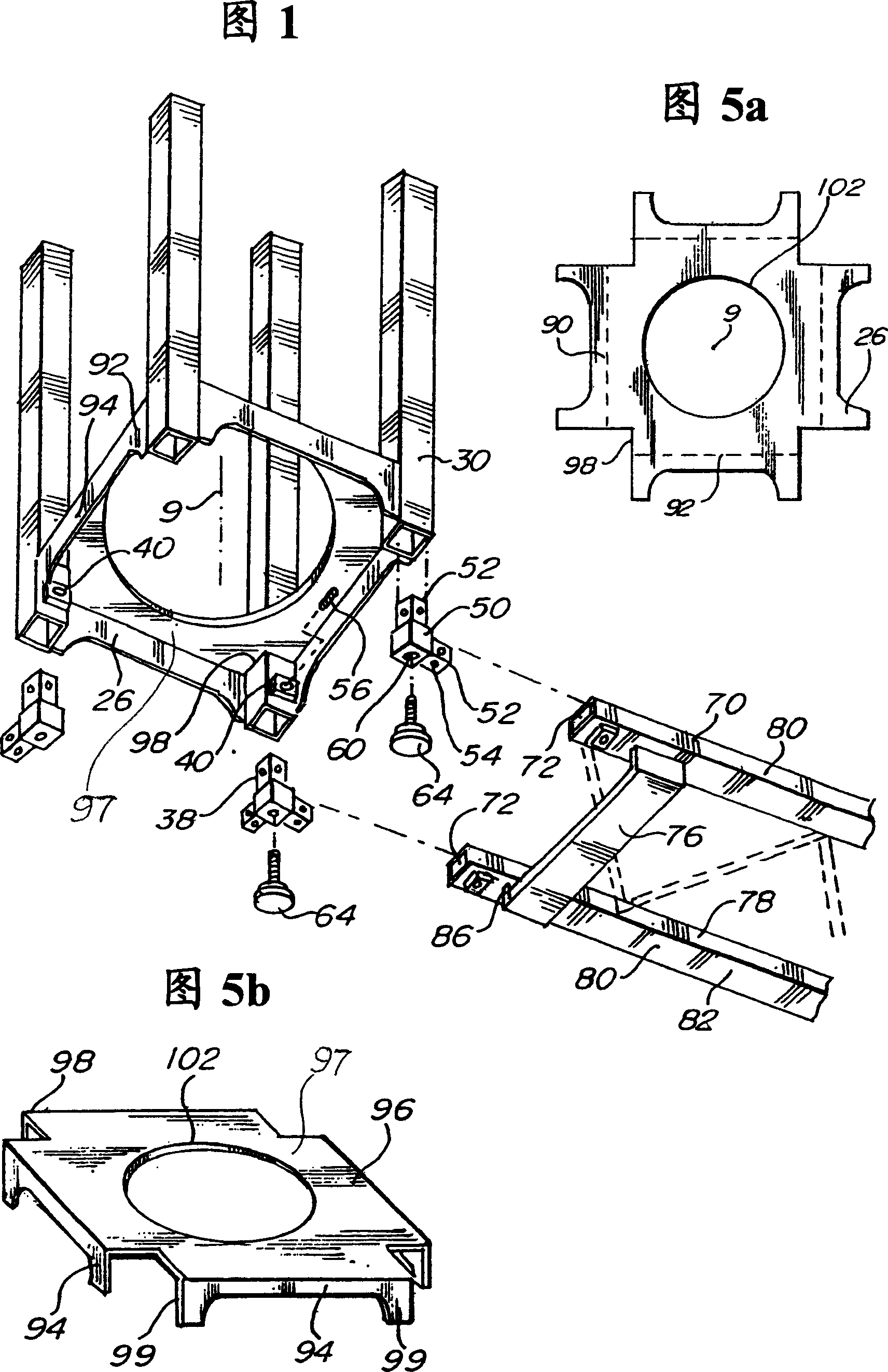
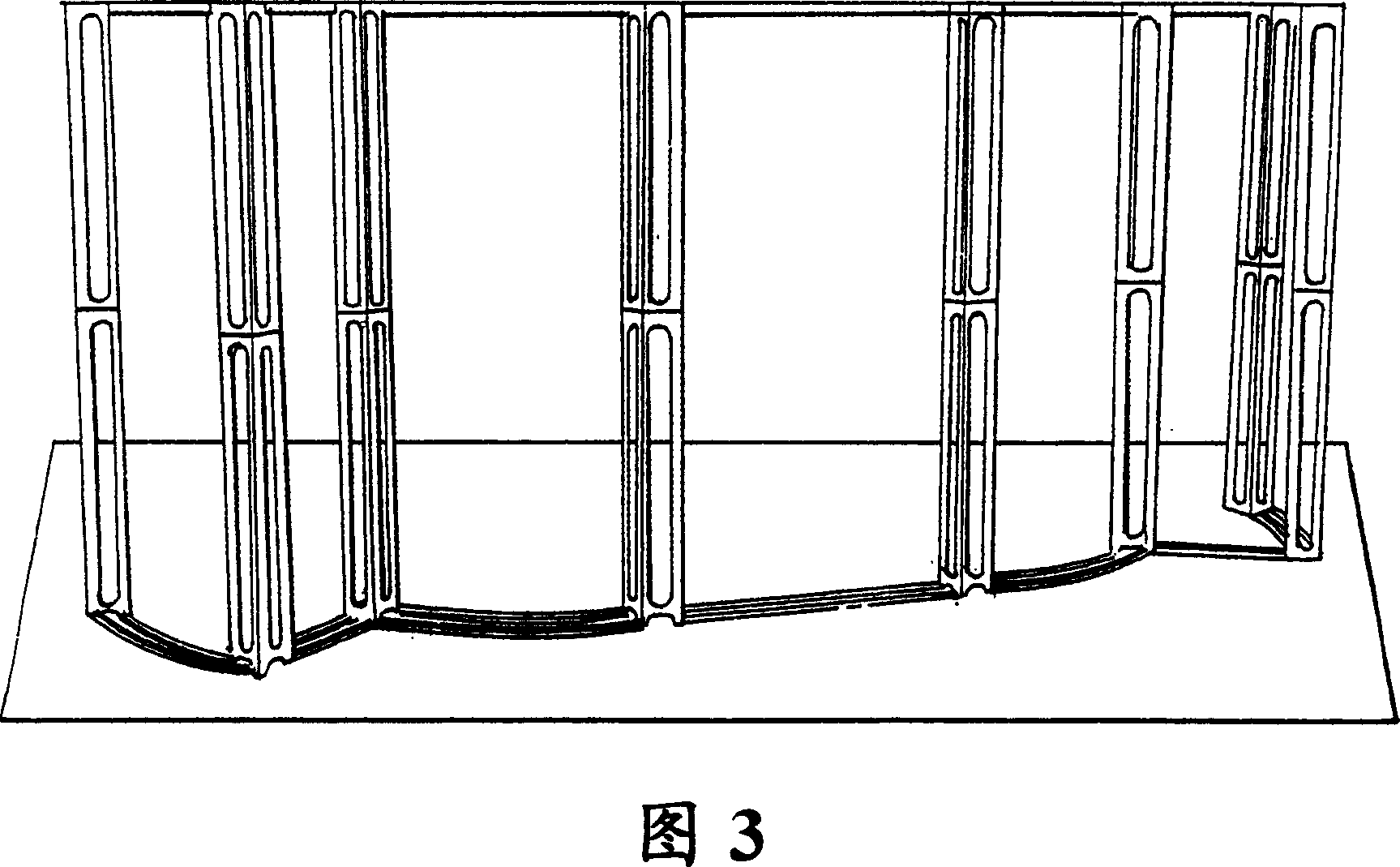
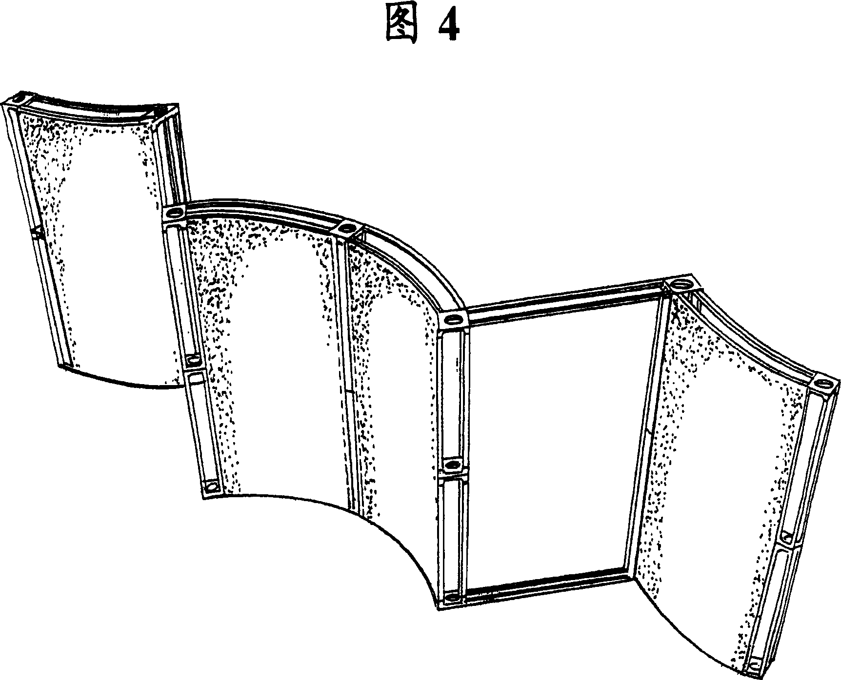
[0026] Embodiments of the present invention will be described below with reference to FIGS. 1 , 2 , 3 and 4 . Referring specifically to FIG. 2 , there is shown an elongated box frame 20 generally comprising four equally sized frame members 22 and a pair of end web members 26 . Each frame member has a first end 27 and a second end 28 . In this embodiment, the frame members extend onto the first end 30 and the second end 31 of the box frame. Each end of the elongated box-shaped frame has a connection portion 32 configured as a socket which is open to receive a male connection portion or connector 38 as shown in FIG. 1 . A threaded portion 40 configured as a nut is welded to an end 44 of the respective frame part 22 .

[0027] The connector 38 generally includes a central body portion 50 and an arrow-shaped connecting portion 52 having a recess 54 for assisting in the positioning of a set screw 56 . Screw holes 60 may be utilized to attach threaded feet 64 or other accessory a...


PUM


Abstract

The elongated box frame structure of the present invention comprises a plurality of frame segments attached to at least one end piece. Preferably, two end pieces are attached, one at each end of the plurality of frame segments. The plurality of frame segments are attached to the end piece such that a column-like structure is formed. The inner space defined within the frame segments is substantially free of webbing. Instead, structural strength and stability is achieved by the attached end pieces. The end pieces of one elongated box frame structure are capable of removably connecting with the end piece of other similar elongated box frame structures to achieve varying framing heights and other dynamic configurations.

Description

technical field [0001] The present invention relates to display appliances, and more particularly to an elongated box-shaped frame assembly in a display display structure. Background technique [0002] In the construction of trade show displays and display racks, multiple trusses and frame structures are traditionally employed to help build and structure the walls that form the backdrop for the defined booth space for a particular vendor. Typically, column and truss structures are designed so that they can be easily disassembled for transport to and from different trade shows. [0003] As a result of this design preference for ease of disassembly, some required structural features arise. Intermediate web members and other forms of cross members generally provide removable pivot points for erecting and dismantling the frame. In addition, web members are typically added to counteract any structural instability that may be induced by the frangible feature, thereby providing a...

Claims


Application Information

Patent Timeline
Patent Type & Authority Patents(China)
IPC IPC(8): E04H12/00E04C3/30F16M11/20F16L41/00A47F5/10E04B1/58E04B2/74E04B2/78E04C3/32E04C3/36
CPCE04B2/7433E04B2/78E04B1/5831E04C3/32E04B2002/7483E04B2001/5856E04C3/36A47F5/105
Inventor M·弗里特舍D·伯格J·约翰森
Owner SKYLINE DISPLAY
Why Eureka
Try Eureka