
Developing apparatus with developer transporting screw

A developing device and developer technology, which are applied in the direction of electric recording process applying charge pattern, equipment for applying electric recording process of charge pattern, electric recording technique, etc. The problem of uneven distribution of agent developer

Inactive Publication Date: 2007-03-28
CANON KK
View PDF5 Cites 0 Cited by
  • Summary
  • Abstract
  • Description
  • Claims
  • Application Information

AI Technical Summary

Problems solved by technology

[0011] The developer moves from the screw 5 to the surface of the developing sleeve 2, and then moves to the opposite part of the photoreceptor 1 with the rotation of the developing sleeve 2. Therefore, the uneven distribution of the developer brought by the above-mentioned screw 5 causes the surface of the developing sleeve 2 to As a result, the image in the longer direction of the photoreceptor 1 has uneven shading (hereinafter referred to as this kind of image defect as "uneven pitch of the screw")
[0012] In particular, such uneven pitch of the screw is very likely to occur when the arrangement of the developing sleeve 2 and the developer conveying screw 5 is designed to be close to each other for downsizing the device.
[0013] In order to avoid unevenness of the pitch of the screw in the image, even if the configuration relationship between the developing sleeve 2 and the screw, the magnetic pole relationship of the magnet in the developing sleeve, the regulation state of the thickness of the developer layer brought by the regulation member 4, etc. Each composition is optimized, but as long as the distribution of the developer conveyed by the screw is skewed due to the pitch of the screw blades, it is difficult to completely prevent
[0014] In addition, in a developing device using a two-component developer having toner and carrier, since the toner concentration of the developer changes according to the balance between toner consumption and replenishment, the amount of the developer increases or decreases during the operation of the device.
Especially when the amount of toner in the developing device is small, it is very difficult to completely prevent the occurrence of uneven pitch of the screw.

Method used


Image

  • Developing apparatus with developer transporting screw
  • Developing apparatus with developer transporting screw
  • Developing apparatus with developer transporting screw

Examples


no. 1 Embodiment approach

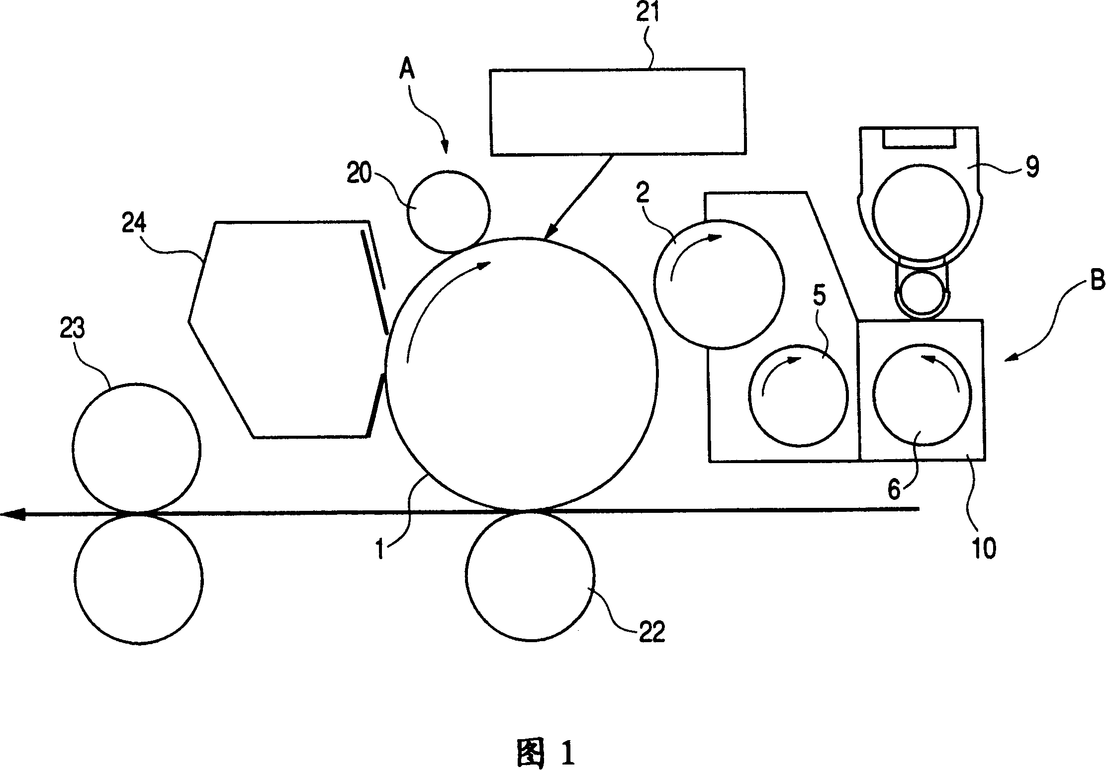
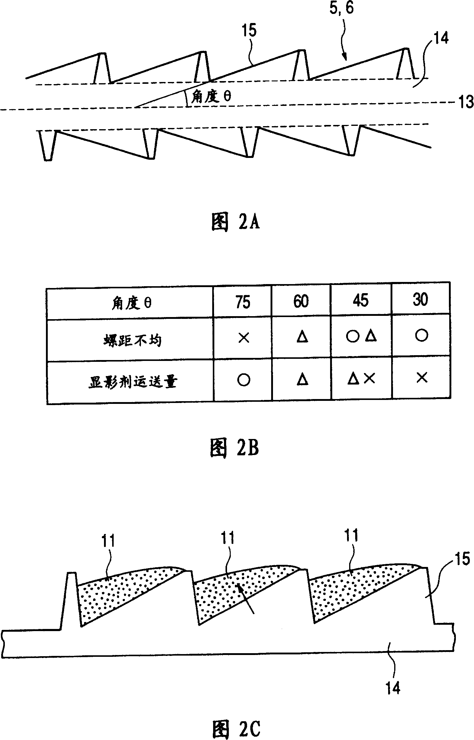
[0041] Next, an image forming apparatus equipped with the developing apparatus of the first embodiment of the present invention will be described with reference to FIG. 1 and FIGS. 2A , 2B and 2C. 1 is a schematic cross-sectional view of the entire image forming apparatus, FIGS. 2A, 2B and 2C show a screw for conveying the developer, FIG. 2A is a view cut through a plane passing through the rotation center line of the screw, and FIG. In the table of the results of the developer conveyance test, FIG. 2C is an explanatory diagram of the state of the developer conveyed by the screw.

[0042] Overall Configuration of Imaging Device

[0043]First, the overall configuration of the imaging device 2A will be roughly described with reference to FIG. 1 . In FIG. 1, 1 is a rotatable photoreceptor drum of a developing carrier, and an electrifying device 20, an exposing device 21, a developing device B, and a transfer device 22 are arranged in this order in the rotation direction of the p...

no. 2 Embodiment approach

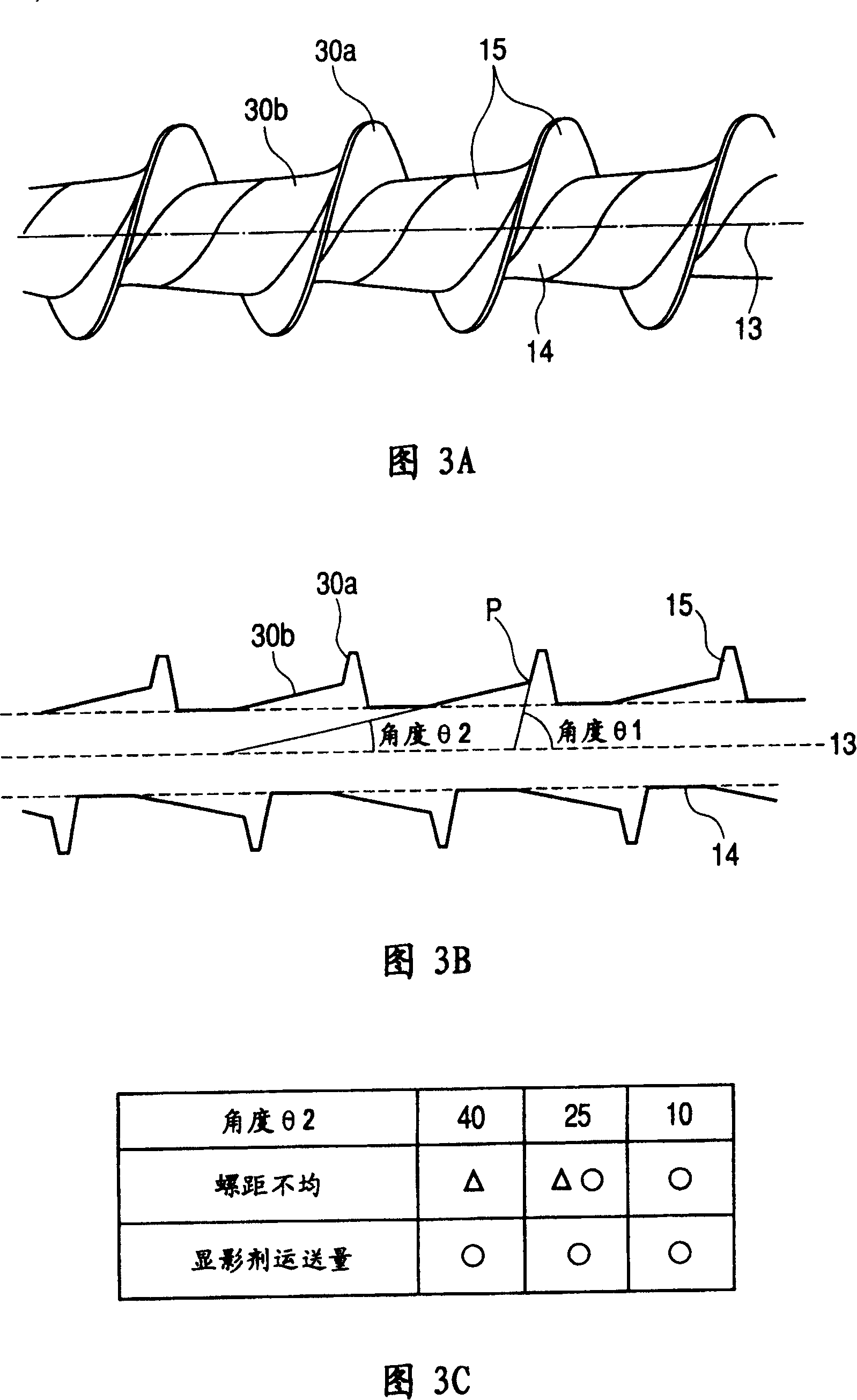
[0058] In contrast to the above-mentioned first embodiment, the conveying surface of the blade of the screw facing the developer conveying direction is constituted by a single plane. Multiple transport surfaces with different inclination angles". The description will be made with reference to FIGS. 3A , 3B and 3C to FIGS. 5A and 5B .

[0059] 3A, 3B and 3C show the screw of the developing device according to the second embodiment, FIG. 3A is an external view of the screw, FIG. 3B is a cross-sectional view cut by a plane passing through the rotation center line of the screw, and FIG. Angle (tilt angle) Result table of developer conveyance test. 4A is an explanatory view of the state in which the developer is conveyed by the screw, and FIG. 4B is a diagram for explaining the distance (height) H1 from the surface (reference surface) of the rotating shaft of the screw to the tip of the blade and the intersection between the reference surface and the two surfaces 30a, 30b A cross...

no. 3 Embodiment approach

[0074] Next, the screw used in the developing device of the third embodiment will be described. 9 and 10 are cross-sectional views cut along a plane passing through the rotation center line of the screw according to the present embodiment, and are views for explaining the angle and the configuration length of the blades, respectively. The developer conveying direction is to the left in the figure.

[0075]The present embodiment is characterized in that a conveyance screw blade (first blade) 15 serving as a conveyance blade portion is helically wound around the shaft of the screw, and is arranged immediately after the conveyance screw blade 15 (developer conveyance blade). An addition screw blade (second blade) 16 as an addition blade portion is separately provided on the upstream side in the direction.

[0076] As shown in FIGS. 9 and 10 , let the angle formed by the conveying surface of the conveying screw blade 15 facing the developer conveying direction and the center line...


PUM


Abstract

Provided is a developing device, etc., having a screw shape which effectively prevents variations in screw pitch. The developing device supplies developer to a developing sleeve by rotating a screw and develops a latent image formed on a photoreceptor drum with developer. The screw has a spiral vane around a rotary shaft. The vane is formed so that an angle between the axis of the rotary shaft and a vane face is <=60[deg.].

Description

technical field [0001] The present invention relates to a developing device mounted on an image forming device of a copier, a printer, etc., in particular, to a developing device with a developer conveying screw. Background technique [0002] As a developing device mounted on an "image forming apparatus using an electrophotographic technique", a developing device using a two-component developer having very good chargeability to toner has been widely used. 7A and 7B show the configuration of a developing device using a general two-component developer, and FIG. 7A is a cross-sectional view and FIG. 7B is an explanatory plan view. [0003] 10 is a developer container containing a developer 11 formed of a toner and a carrier. A portion close to the opposite side of the photoreceptor drum 1 of the developer container 10 is provided with an opening portion provided with a developing sleeve 2 as a developer carrier. The developing sleeve 2 is a hollow non-magnetic metal sleeve, a...

Claims


Application Information

Patent Timeline
Patent Type & Authority Patents(China)
IPC IPC(8): G03G15/08G03G15/01
CPCG03G2215/0827G03G2215/0822G03G15/0839G03G15/0893G03G15/0877
Inventor 山口诚士木下正英沼上敦村山一成上野隆人宇山雅夫
Owner CANON KK
Learn More