Air conditioning device with floor heating function

An air-conditioning device and floor technology, which is applied to air-conditioning systems, machine operation methods, refrigerators, etc., can solve problems such as dehumidification that cannot be solved well

Inactive Publication Date: 2007-05-02
ミサワ環境技術
View PDF2 Cites 0 Cited by
  • Summary
  • Abstract
  • Description
  • Claims
  • Application Information

AI Technical Summary

Problems solved by technology

[0003] In the past air conditioners, the switch of the knob 25 is used to determine which side of the liquid medium is sent from the cold and heat source machine 20 or the warm and heat source machine 21 to the air duct 22, so the cooling and heating in the basic sense are possible. Satisfied, but not a good solution to the problem of dehumidification

Method used


Image

  • Air conditioning device with floor heating function
  • Air conditioning device with floor heating function
  • Air conditioning device with floor heating function

Examples


Embodiment Construction

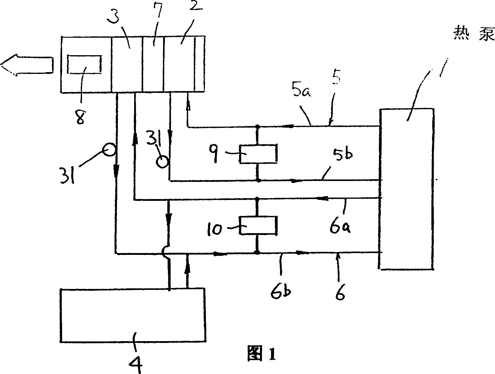
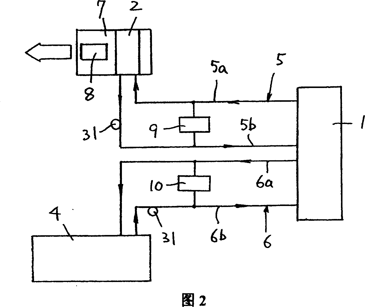
[0012] The embodiment of the air conditioner with floor heating function in the present invention is shown in FIG. 1 . In this air conditioner, the heat pump 1 and the low-temperature heat radiation part 2 are connected through the low-temperature liquid pipeline 5 installed in a circular manner, and the same heat pump 1 and the high-temperature heat radiation part 3 are installed in a circular manner. The high temperature liquid with the same inlet 6a and circuit 6b is connected with the pipeline 6, and the heat release part 4 of the floor heating is connected with the inlet 6a of the high temperature liquid pipeline 6 and the circuit 6b.

[0013] Low-temperature heat radiation part 2 is housed in the upper area in the air guide pipe 7 in which blower fan 8 is housed, and high-temperature heat radiation part 3 is housed in its lower area simultaneously. The low-temperature liquid pipeline 5 communicates with the low-temperature liquid tank 9 storing low-temperature liquid, an...


PUM


Abstract

Provided are an air conditioner with a dehumidifying function and a floor heating function as well as the cooling and heating functions. A heat pump 1 and a low-temperature heat radiating part 2 are circulatively communicated with each other by a low-temperature liquid pipe 5 having a first outward path 5a and a first return path, and the heat pump 1, a high-temperature heat radiating part 3, and a floor heating heat radiating part 4 are circulatively communicated with one another by a high temperature liquid pipe 6 having a second outward path 6a and a second return path 6b. The low-temperature heat radiating part 2 is provided in the upstream side of an air guide duct 7 having a blow 8 and the high-temperature heat radiating part 3 is provided in its downstream side. This constitution allows this air conditioner to perform cooling, heating, dehumidifying, and floor heating.

Description

technical field [0001] The present invention relates to an air conditioner having a dehumidification function and a floor heating function in addition to cooling and heating functions. Background technique [0002] As shown in FIG. 3 , the original air conditioner is equipped with a cold and heat source machine 20 , a warm and heat source machine 21 and an air duct 22 . For example, in summer, the liquid medium is sent from the cold and heat source machine 20 to the heat radiation part 23 in the air duct 22, and the cold air is provided from the blower 24 to the room, or in winter, by adjusting the knob 25, the cold medium is changed from warm to warm. The source equipment 21 is sent to the heat radiation part 23 in the air duct 22, and the warm air is supplied to the room from the blower 24. Contents of the invention [0003] In the past air conditioners, the switch of the knob 25 is used to determine which side of the liquid medium is sent from the cold and heat source ...

Claims


Application Information

Patent Timeline
Patent Type & Authority Patents(China)
IPC IPC(8): F24F3/00F25B30/00F24D7/00F25B29/00
Inventor 洲泽昭已
Owner ミサワ環境技術
Why Eureka
Try Eureka