Dehumidifying handcart for moving-open style switchgear

A switchgear and wet handcart technology, applied in pull-out switchgear, switchgear, electric vehicles, etc., can solve problems such as inability to place and use, potential safety hazards of power transmission and transformation equipment, unrealistic power outages, etc. The effect of solving the problem of inconvenient access to electricity and preventing discharge

Inactive Publication Date: 2016-02-03
FUJIAN PUTIAN LIYUAN ELECTRICAL EQUIP
View PDF6 Cites 0 Cited by
  • Summary
  • Abstract
  • Description
  • Claims
  • Application Information

AI Technical Summary

Problems solved by technology

[0002] Commonly used dehumidification devices generally use Freon and other refrigerants as the cooling source, which has good cooling effect and good dehumidification effect, but the volume is too large to be placed in the switch cabinet.
At present, the dehumidification devices of switch cabinets produced at home and abroad all adopt the heater type, that is, when the humidity in the cabinet exceeds the specified value, the heating plate is started to heat up, so that the water in the air evaporates, and when the water evaporates, it condenses on the top of the cabinet to form The water drops freely, that is, the moisture in the cabinet can never be discharged from the cabinet, causing safety hazards to the power transmission and transformation equipment in the cabinet
Secondly, traditional dehumidification devices are generally fixedly installed in the switchgear. When the dehumidification equipment needs to be maintained, it is unrealistic to shut down the switchgear and cause a power outage. However, if maintenance is live, personal safety cannot be guaranteed. Therefore, causing It is difficult to maintain the dehumidification device in the switch cabinet
Thirdly, due to the high operating power and voltage of the switchgear, if some equipment (such as dehumidification device) attached to the switchgear or on the handcart is directly powered from the switchgear, it may cause direct damage or short service life. , it is inconvenient for the auxiliary equipment to take power directly from the switch cabinet

Method used


Image

  • Dehumidifying handcart for moving-open style switchgear
  • Dehumidifying handcart for moving-open style switchgear
  • Dehumidifying handcart for moving-open style switchgear

Examples


Embodiment Construction

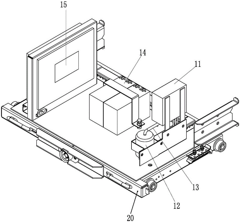
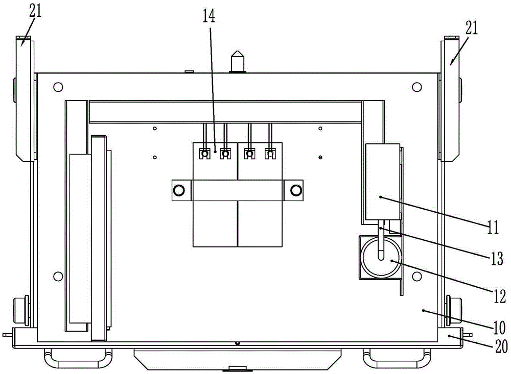
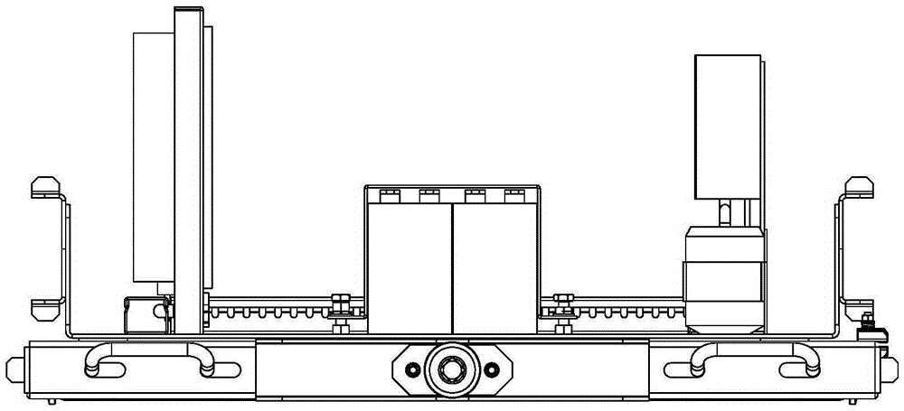
[0018] look up Figure 1 to Figure 3 , a dehumidifying handcart for a removable switchgear, which includes a handcart body 10, a valve lifter 21 is provided on the chassis 20 below the handcart body 10, and a semiconductor refrigeration dehumidification device 11 is installed on the handcart body 10 .

[0019] The semiconductor refrigeration and dehumidification device 11 has a hot end and a cold end. A circulating dehumidification fan (not shown) is installed near the hot end of the handcart body 10, and a closed water storage cup is detachably installed at the near cold end of the handcart body. 12 is used to receive the condensed water condensed at the cold end. The cold end of the semiconductor refrigeration dehumidification device 11 can be connected to the water storage cup 12 through the water conduit 13 and the condensed water can be introduced into the water storage cup 12 . Using semiconductor refrigeration technology, the cold end condenses the moisture in the air ...


PUM


Abstract

The invention discloses a dehumidifying handcart for a moving-open style switchgear. The handcart comprises a moving handcart body. Shutter lifters are arranged on a base disk at the lower part of the handcart body. A semiconductor refrigeration dehumidifying device is installed on the handcart body. The semiconductor refrigeration dehumidifying device comprises a hot end and a cool end. A circulating dehumidifying fan is installed near the hot end of the handcart body. An enclosed water storage cup for holding condensation water condensed from the cool end is detachably installed near the cool end of the handcart body. A DC battery supplying the semiconductor refrigeration dehumidifying device with working power is detachably installed near the hot end of the handcart body. A humidity measurement device for measuring the humidity inside the handcart is also installed near the cool end of the handcart body. The handcart facilitates maintenance of the dehumidifying device, realizes drying and dehumidifying inside a shutter, discharges moisture from inside to outside of a switchgear, keeps appropriate air humidity inside the switchgear, takes power from the DC battery directly, and thereby solves the problem of inconvenient power taking of the switchgear.

Description

technical field [0001] The invention relates to a switch cabinet handcart, in particular to a dehumidifying handcart for a removable switch cabinet. Background technique [0002] Commonly used dehumidification devices generally use refrigerants such as freon as a cooling source, which has good cooling effect and good dehumidification effect, but is too bulky to be placed in a switch cabinet. At present, the dehumidification devices of switch cabinets produced at home and abroad all adopt the heater type, that is, when the humidity in the cabinet exceeds the specified value, the heating plate is started to heat up, so that the water in the air evaporates, and when the water evaporates, it condenses on the top of the cabinet to form The water drops freely, that is, the moisture in the cabinet can never be discharged from the cabinet, which poses a safety hazard to the power transmission and transformation equipment in the cabinet. Secondly, traditional dehumidification device...

Claims


Application Information

Patent Timeline
IPC IPC(8): H02B11/167H02B1/28H02J7/00
CPCH02B11/167H02B1/28H02J7/00
Inventor 陈晓勇陈道华许金耀吴伟明
Owner FUJIAN PUTIAN LIYUAN ELECTRICAL EQUIP
Why Eureka
Try Eureka