
Scissors type lifting equipment

A lifting equipment, scissor-type technology, applied in the direction of lifting devices, lifting frames, etc., can solve the problems of large force introduction and deviation, and achieve the effects of reducing control costs, avoiding transformation, and small wear

Active Publication Date: 2007-05-16
PRO HUB HEBETECHN
View PDF8 Cites 0 Cited by
  • Summary
  • Abstract
  • Description
  • Claims
  • Application Information

AI Technical Summary

Problems solved by technology

In this case also large deviations of the force introduction occur

Method used


Image

  • Scissors type lifting equipment
  • Scissors type lifting equipment
  • Scissors type lifting equipment

Examples


Embodiment Construction

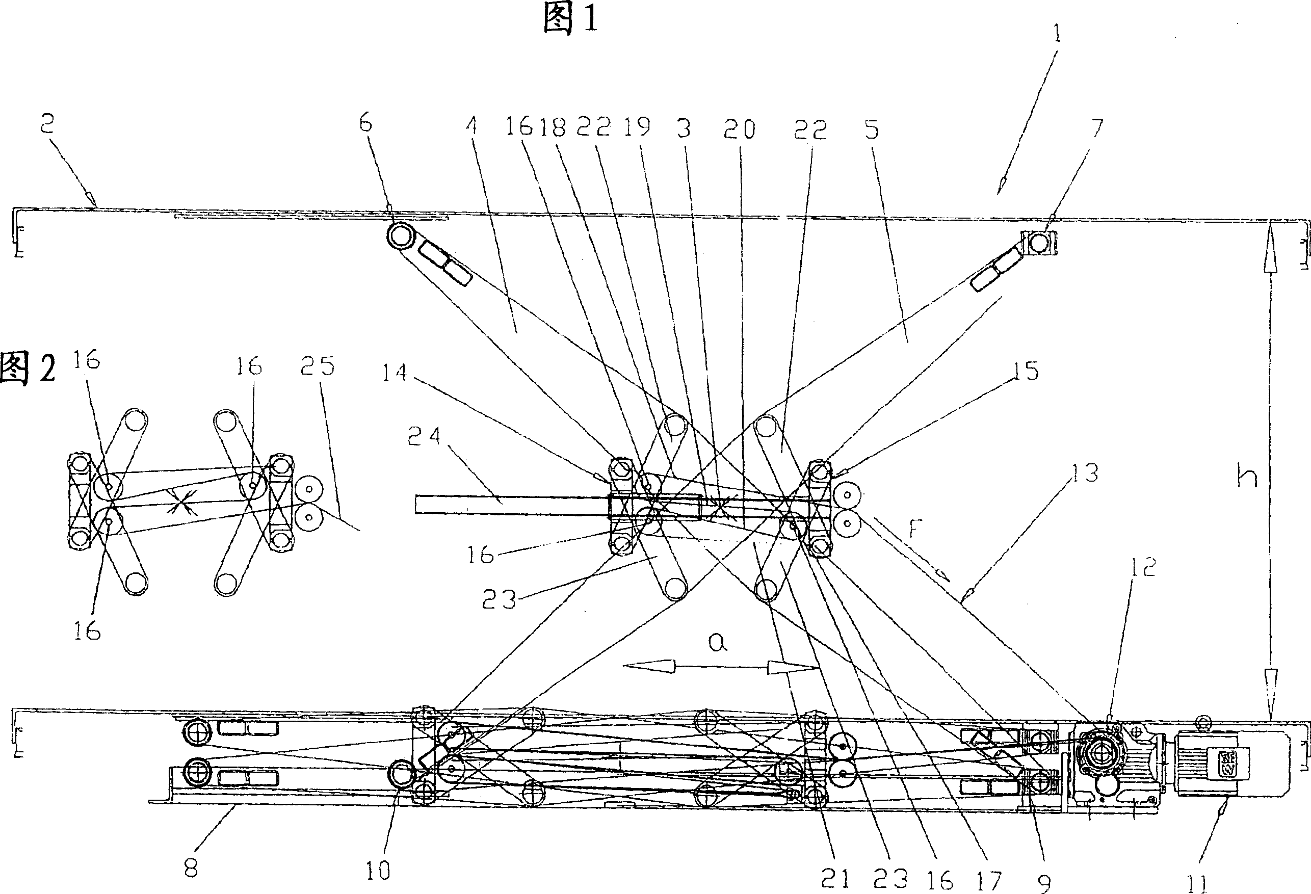
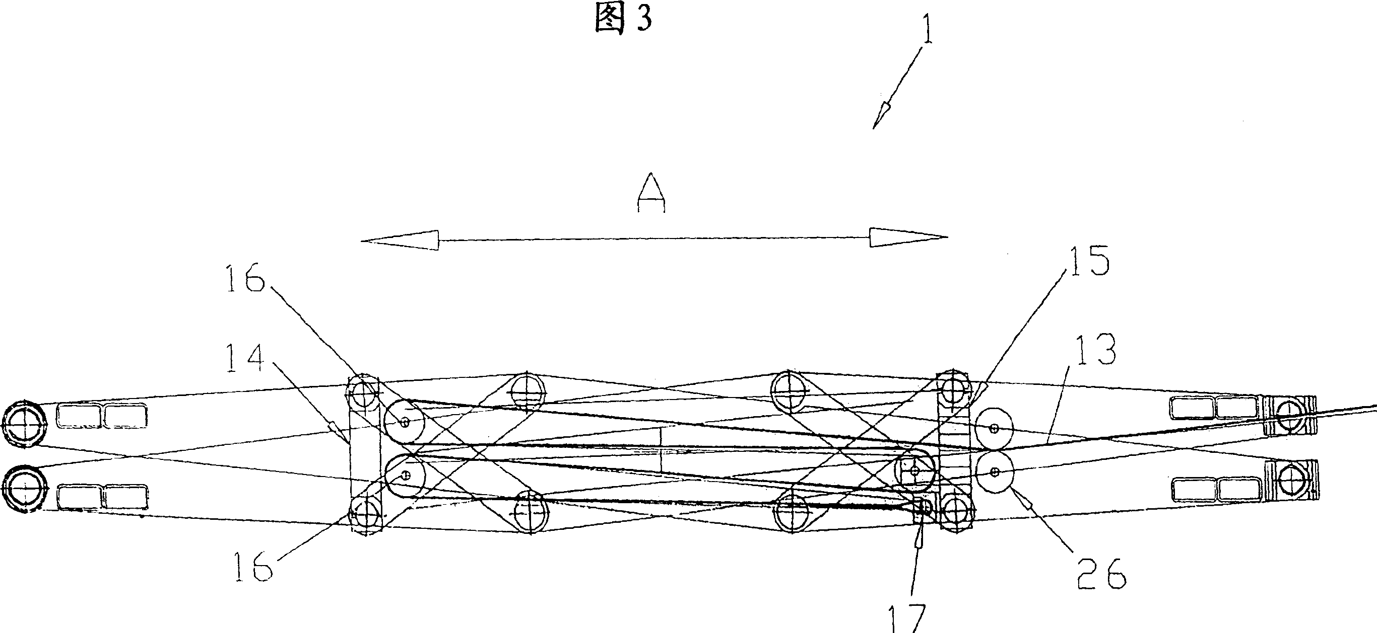
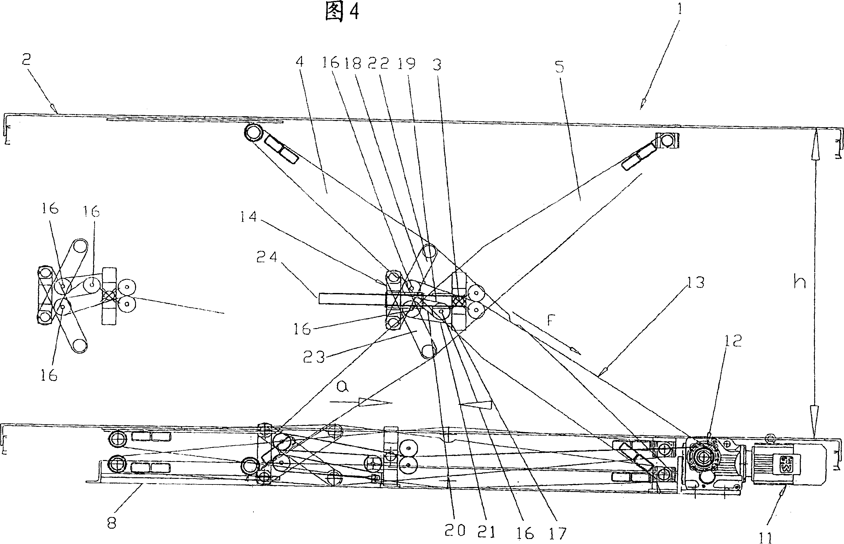
[0028]Fig. 1 shows a side view of the scissor lifting device 1 of the present invention. The scissor lifting device 1 has two scissor arms 4, 5 arranged under the lifting plane 2 and connected in pairs by a swing shaft 3, wherein the swing shaft 3 is set on the corresponding supporting lifting planes of the scissor arms 4, 5 The center between the ends 6, 7 of 2 and the ends 9, 10 supported on the bottom surface 8. The scissor lifting equipment 1 is equipped with a driving device 11 fixedly arranged on the bottom surface 8, and a traction tool 13 configured as a conveyor belt is provided on the reel 12 for raising and lowering the scissor arms 4 and 5. For this purpose, the scissor lifting equipment 1 is equipped with two parallel connection bridges 14, 15 arranged on both sides of the swing shaft 3, wherein the first connection bridge 14 is equipped with at least two steering rollers 16 and the second connection bridge 15 is equipped with A steering roller 16 and a fixing member ...


PUM


Abstract

A scissor lift mechanism (1) having at least two scissor elements (4, 5) connected in pairs by a swivel axis (3). The drive (11) for raising and lowering the scissor elements (4, 5) is provided by a traction member (13). To reduce the driving power required for operation while at the same time reducing control complexity, the scissor lift mechanism (1) is equipped with two coupling bridges (14, 15) situated on opposite sides of the swivel axis (3) and pivotably supported by thrust struts (22, 23) on each of the two scissor elements (4, 5), respectively. The distance 'a' between the coupling bridges (14, 15) and the resulting height of lift 'h' are easily variable by applying a tractive force 'F' via the traction member (13, 25) which is guided around reversing rollers (16) and back and forth along a plurality of generally parallel paths (18, 19, 20, 21) between the two coupling bridges (14, 15).

Description

Technical field [0001] The present invention relates to a scissor-type lifting equipment, which has at least two pair of scissor arms connected by a swing shaft, wherein the swing shaft is arranged between each end of the scissor arm, and has a driving device for using A traction tool lifts and lowers the scissors arm. Background technique [0002] One such scissor lifting device is, for example, the target of DE 100 24 075 A1. Among them, the distance between the upper ends or the lower ends of the scissors arms is changed by the traction tool. To this end, the traction tool is connected to one end of a scissor arm and connected to the drive device by means of a steering roller at the upper end of the other scissor arm, so that the above-mentioned distance change can be achieved. The traction tool acts on a supporting body and the latter is located near the lower end of the scissor arm between the lower end of one scissor arm and the upper end of the support of the other scissor...

Claims


Application Information

Patent Timeline
Patent Type & Authority Patents(China)
IPC IPC(8): B66F7/06
CPCB66F7/065
Inventor 米夏埃尔·考夫曼
Owner PRO HUB HEBETECHN
Learn More