Snap fit mechanism

A technology of engaging claws and fixing components, applied in the direction of fasteners, connecting components, mechanical equipment, etc., can solve the problems of release, inadvertent engagement, and disengagement of the engaging claws, so as to reduce the amount of elastic deformation and prevent inadvertent release. The effect of snapping

Inactive Publication Date: 2007-06-20
MITSUBISHI ELECTRIC CORP
View PDF3 Cites 0 Cited by
  • Summary
  • Abstract
  • Description
  • Claims
  • Application Information

AI Technical Summary

Problems solved by technology

That is: because the elastic tongue of the conventional snap-fit ​​mechanism is inserted into the through-hole of the plate-shaped part, and the engaging claw is engaged with the edge of the through-hole, the plate-shaped part can be fixed. However, After the plate parts are fixed, in the case where, for example, the fingers of the operator contact the front end of the elastic tongue exposed from the through hole during the assembly operation, since the top surface is formed at the front end of the elastic tongue, and it is adjacent to the top surface. Since the inclined surface of the engaging claw is formed so that the elastic tongue is elastically deformed inwardly due to the load received on the inclined surface of the engaging claw, in this case, there is a problem that the engaging claw passes through the through hole of the plate-shaped part. The edge part of the device comes out, so that the engagement of the conventional snap-fit ​​mechanism with respect to the plate-shaped part is inadvertently released

Method used


Image

  • Snap fit mechanism
  • Snap fit mechanism
  • Snap fit mechanism

Examples


Embodiment Construction

[0015] Embodiments of the present invention will be described below.

[0016] [Embodiment 1]

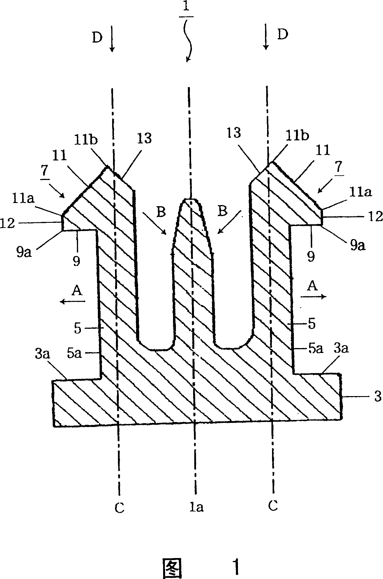
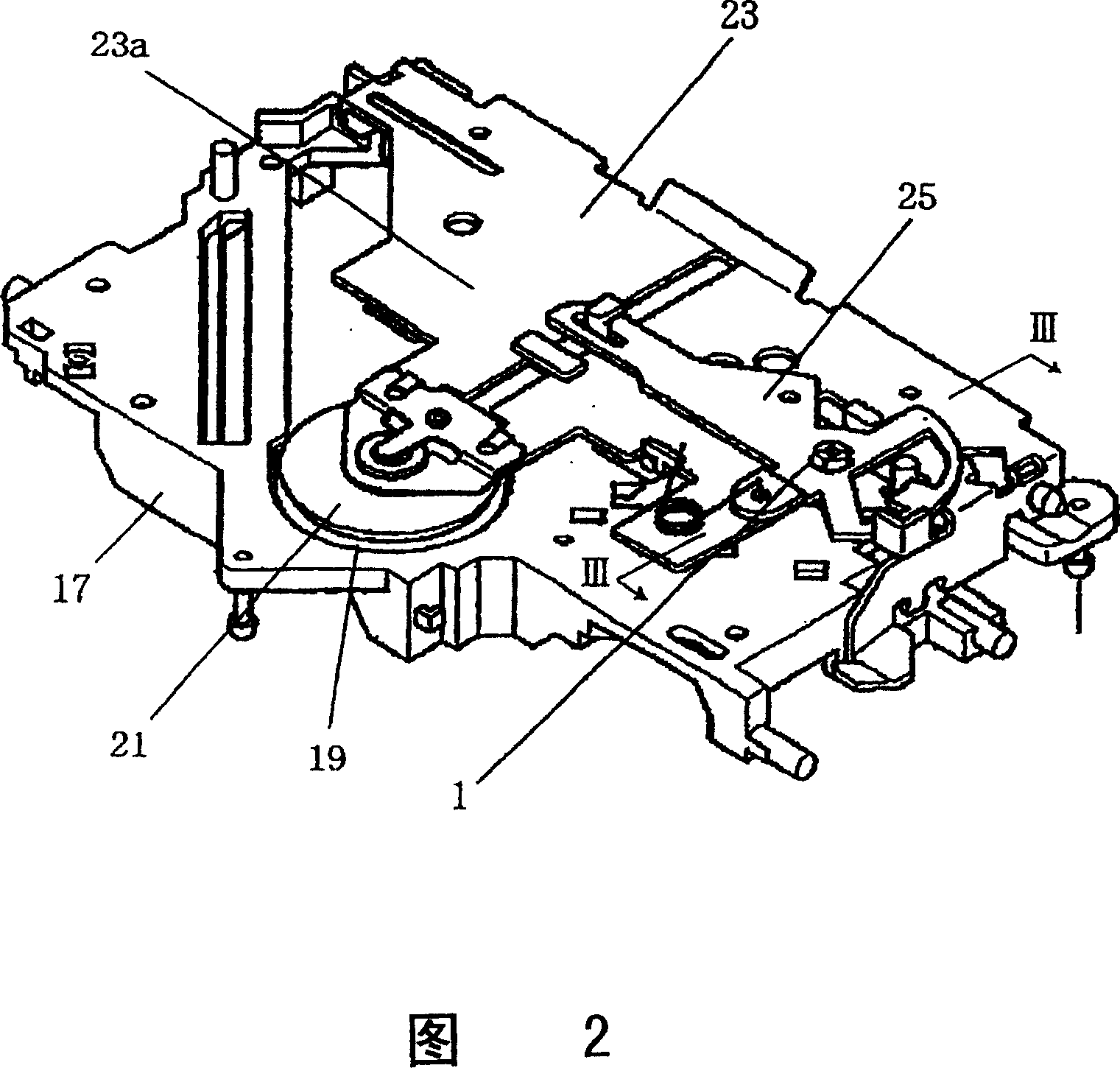
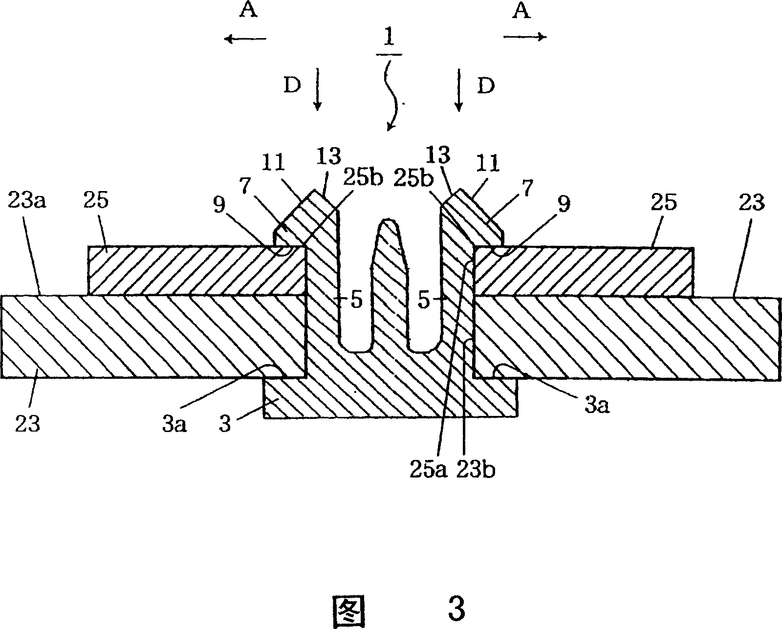
[0017] Fig. 1 is a sectional view showing a snap-fit ​​mechanism according to Embodiment 1 of the present invention, Fig. 2 is a schematic perspective view showing an example of fixing parts of a disc playback device by applying the fitting mechanism shown in Fig. 1 , and Fig. 3 is a diagram Sectional view of line III-III of 2. In addition, this first embodiment is an application example in which two plate-shaped parts (members to be fixed) in a stacked state are fixed through through holes formed in both parts with a common inner diameter.

[0018] As shown in FIG. 1, the snap fit mechanism 1 roughly includes: a plate-shaped base 3 having a planar upper surface (first fixing surface) 3a; There are 4 in 1, but only 2 are shown in Fig. 1 and Fig. 3) elastic tongue 5;

[0019] The engaging claw 7 roughly includes: a side surface (second fixing surface) 9 for fixing a plate-shaped pa...


PUM


Abstract

A snap fit mechanism has an elastic tongue provided on a base of the mechanism. On the tip of the tongue is provided an engaging claw that has an engaging inclined face. A far end of the engaging inclined face from the base is arranged so as to be located between the outside face of the elastic tongue and the centerline C in a longitudinal direction of the elastic tongue. Further, on the tip of the elastic tongue is provided an engagement-maintaining inclined face which gives an outward load to the elastic tongue on receiving an accidental load thereon so as to reduce the inward elastic deformation of the elastic tongue, thereby preventing the accidental release of the engagement of the tongue.

Description

technical field [0001] The present invention relates to, for example, a snap-fit ​​mechanism for fixing components provided in a disc playback device. Background technique [0002] Patent Document 1 discloses a conventional snap-fit ​​mechanism provided on electric equipment and its accessories. A conventional snap-fit ​​mechanism is composed of a first engaging portion provided on the electrical equipment side and a second engaging portion provided on the case side as an accessory. The first engaging part has a recess formed on the side of the air device and a pair of protrusions formed on the recess to reduce the opening area, and the second engaging part has a front end protruding from a plane of the housing and The elastic tongue pieces of the pair of engaging claws respectively elastically engage with the pair of protrusions of the first engaging portion. Each engaging claw is composed of a side surface extending laterally from the front end of the elastic tongue and ...

Claims


Application Information

Patent Timeline
Patent Type & Authority Patents(China)
IPC IPC(8): H01H50/04F16B5/06F16B19/00A44B99/00F16B21/08
CPCF16B21/088Y10S411/913F16B5/0642Y10T24/44026
Inventor 粟藏善文谷口和寿菊地英明
Owner MITSUBISHI ELECTRIC CORP
Why Eureka
Try Eureka