Scroll apparatus with an axial gap control function

a technology of axial gap control and scroll compressor, which is applied in the direction of machines/engines, rotary/oscillating piston pump components, liquid fuel engines, etc., can solve the problems of increasing frictional force, reducing the life of use and reliability of scroll compressors, and leaking into the chamber of scroll compressors. to achieve the effect of reducing frictional for

Active Publication Date: 2007-10-02
IND TECH RES INST
View PDF12 Cites 7 Cited by
  • Summary
  • Abstract
  • Description
  • Claims
  • Application Information

AI Technical Summary

Benefits of technology

[0012]Therefore, it is a primary objective of the present invention to provide a scroll apparatus with an axial gap control function and makes use of the axial compliance to give effectively a fixed gap control function (producing the maximum gap for the total axial displacement) when the scroll apparatus is shut down so as to reduce the frictional force at the start-up stage and the noise produced during its operation.
[0013]Another objective of the present invention is to provide a scroll apparatus with an axial gap control function and adopts a suspension design for its axial compliance. When the scroll apparatus is operating, a lateral side top of the fixed scroll when pressed by external forces still can effectively use a small elastic deformation produced by a specially installed flexible element to restrict the fixed scroll for an axial compliance only and being closely attached on the top of the orbiting scroll, and thus can further prevent a leak of the compression chamber.
[0014]Another further objective of the present invention to provide a scroll apparatus with an axial gap control function that effectively restricts the axial movement of the fixed scroll from moving with respect to any other components during the compression process, and uses its flexible element to prevent the axial and rotary movements of the fixed scroll so as to avoid the collisions between the metal components, improve the noise problem of the scroll apparatus (compressor), avoid damages to the component of the scroll apparatus, and enhance the performance and reliability of the scroll apparatus.

Problems solved by technology

Firstly, when the traditional scroll compressor shuts down, its fixed scroll is in contact with its orbiting scroll, thus giving rise to an increase of frictional force when the scroll compressor is started again.
However, the flange, positioning pin and axial gap plate collide with each other during the operation of the scroll compressor, not only making noise, but also giving rise to a leak to the chamber of the scroll compressor.
Further, improper wear will occur at the lateral surface and the end surface between the fixed scroll and the orbiting scroll and will reduce the life of use and the reliability of the scroll compressor.
In present scroll compressor related patents, each of these prior arts has its advantages and disadvantages, but none of them can totally overcome the aforementioned shortcomings.
Its disadvantages include an increased number of components (press plate), a louder noise (rotation and axial gap) and a large stan-up frictional force.
Its disadvantages include an increased number of components and a more complicated axial gap control, which causes a breakdown easily.
However, the axial gap control between the two scrolls is still too complicated and will cause a breakdown easily due to its improper control method.
In other words, the aforementioned prior arts have their advantages and disadvantages, but none of them can totally overcome the shortcomings of the prior arts and definitely require further improvements.

Method used


Image

  • Scroll apparatus with an axial gap control function
  • Scroll apparatus with an axial gap control function
  • Scroll apparatus with an axial gap control function

Examples


Embodiment Construction

[0020]The above and other objects, features and advantages of the present invention will become apparent from the following detailed description taken with the accompanying drawing.

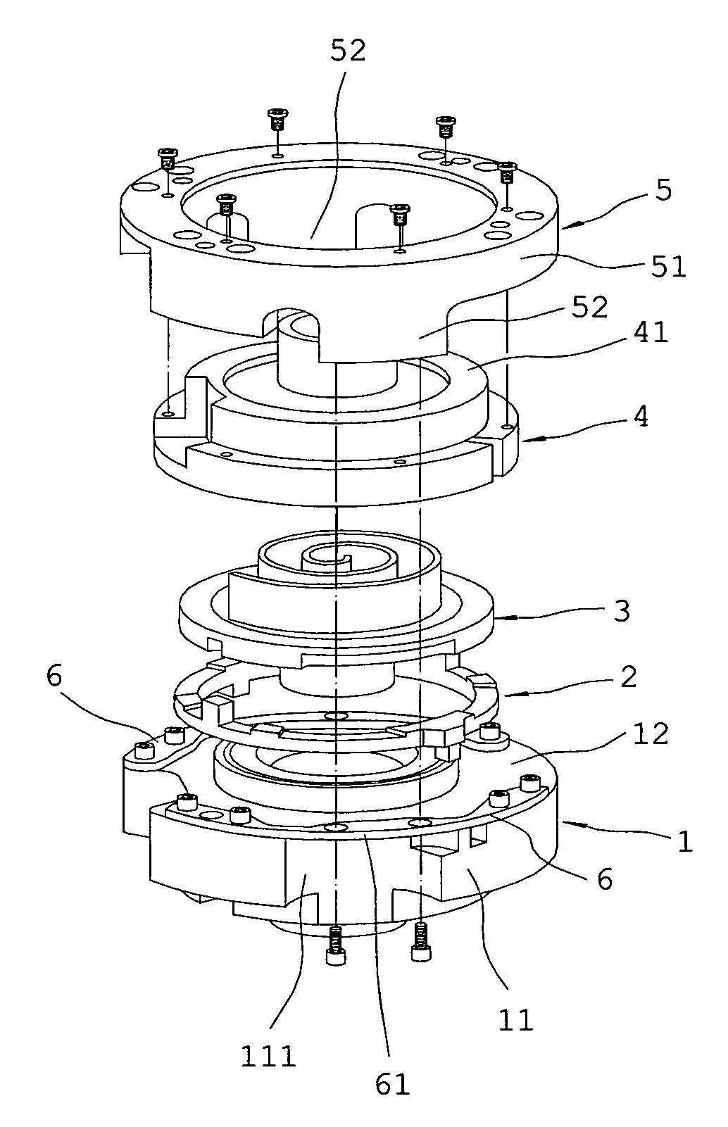
[0021]Reference is made to FIG. 3 for a scroll apparatus with an axial gap control function according to the present invention, which particularly provides a fixed gap control function when the scroll apparatus is shut down, so as to reduce the frictional force at the start-up stage and the noise produced during its operation. The scroll apparatus comprises an orbiting scroll 3, a fixed scroll 4, a positioning ring 5, a flexible element 6, and a frame 1 installed inside a housing (not shown in the figure) of the scroll apparatus.

[0022]The frame 1 is disposed inside the housing (not shown in the figure) of the scroll apparatus, and a pair of indentations 111 is disposed at the periphery 11 of the frame 1.

[0023]The pair of flexible elements 6 are, for example, of a metal beam type and disposed along the per...


PUM


Abstract

A scroll apparatus with an axial gap control function is described. The scroll apparatus is capable of controlling the axial gap between its fixed scroll and orbiting scroll. The scroll apparatus has a frame with a pair of indentations installed in the casing of the scroll apparatus, a pair of flexible elements installed at the lateral side top of the frame and spanning the pair of indentations for defining a suspended flexible segment at the span, a sidewall having a positioning ring with a downward protruding body corresponding to the indentation, in which the protruding body of the positioning ring is fixed to the flexible segment of the flexible element, a fixed scroll suspended at the positioning ring, and an orbiting scroll for orbiting into the fixed scroll.

Description

BACKGROUND OF THE INVENTION[0001]1. Field of the Invention[0002]The present invention relates to a scroll apparatus with an axial gap control function, and more particularly to a scroll apparatus capable of controlling the axial gap between a fixed scroll and an orbiting scroll of the scroll apparatus.[0003]2. Description of Related Art[0004]As a traditional scroll apparatus such as a scroll compressor inevitably comes with two substantial drawbacks as described below.[0005]Firstly, when the traditional scroll compressor shuts down, its fixed scroll is in contact with its orbiting scroll, thus giving rise to an increase of frictional force when the scroll compressor is started again.[0006]Secondly, the flange disposed at the top of a frame, a positioning pin and an axial gap plate are fixed at their center to prevent the fixed scroll from rotating. However, the flange, positioning pin and axial gap plate collide with each other during the operation of the scroll compressor, not only...

Claims


Application Information

Patent Timeline
Patent Type & Authority Patents(United States)
IPC IPC(8): F03C2/00F04C2/00
CPCF01C1/0215F04C27/005F04C18/0215
Inventor LIANG, KUN-YIHUANG, SHU-ERYANG, CHUN-CHUNGCHANG, YU-CHOUNGCHEN, HUNG-CHI
Owner IND TECH RES INST
Why Eureka
Try Eureka