Method for improving laser shock precision and efficiency of weak rigidity parts

A laser shock and weak stiffness technology, applied in heat treatment equipment, heat treatment process control, manufacturing tools, etc., can solve problems affecting laser shock strengthening, changing the position of laser processing, reducing processing efficiency, etc., to achieve precise processing and reduce recovery Time, efficiency improvement effect

Active Publication Date: 2018-12-18
GUANGDONG UNIV OF TECH
View PDF5 Cites 8 Cited by
  • Summary
  • Abstract
  • Description
  • Claims
  • Application Information

AI Technical Summary

Problems solved by technology

If the next laser shock is performed before the elastic deformation of the part has recovered, the shape of the laser spot will change, which will affect the size and energy distribution of the laser power acting on the target, and will also change the position of the laser processing. Ultimately affect the effect of laser shock peening
If you wait for a long enough time, the next laser shock will be performed after the elastic deformation is fully recovered, which will significantly reduce the processing efficiency

Method used


Image

  • Method for improving laser shock precision and efficiency of weak rigidity parts
  • Method for improving laser shock precision and efficiency of weak rigidity parts
  • Method for improving laser shock precision and efficiency of weak rigidity parts

Examples


Embodiment 1

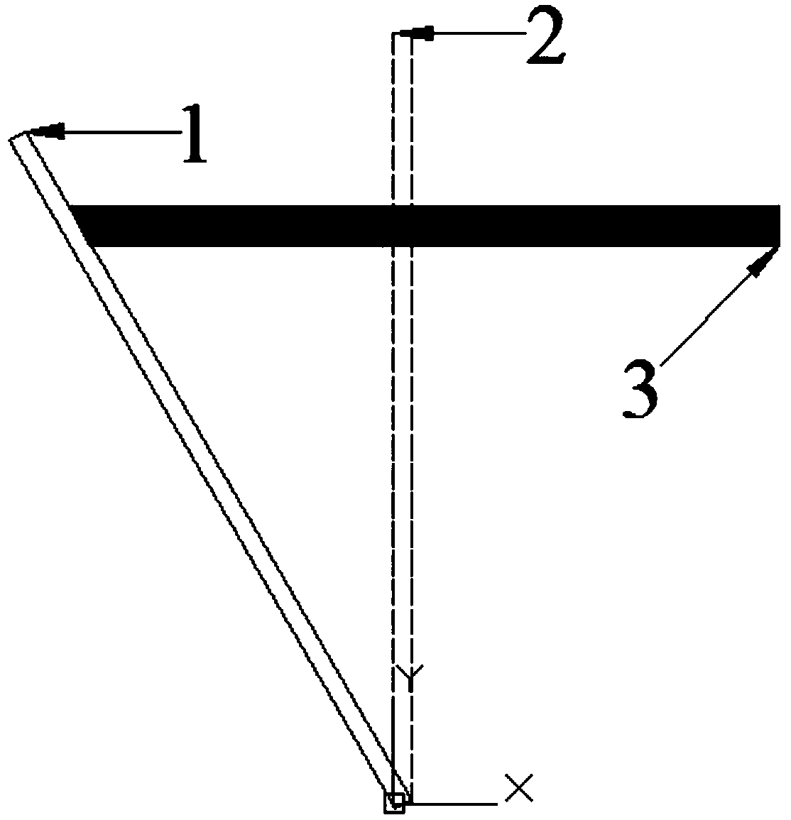
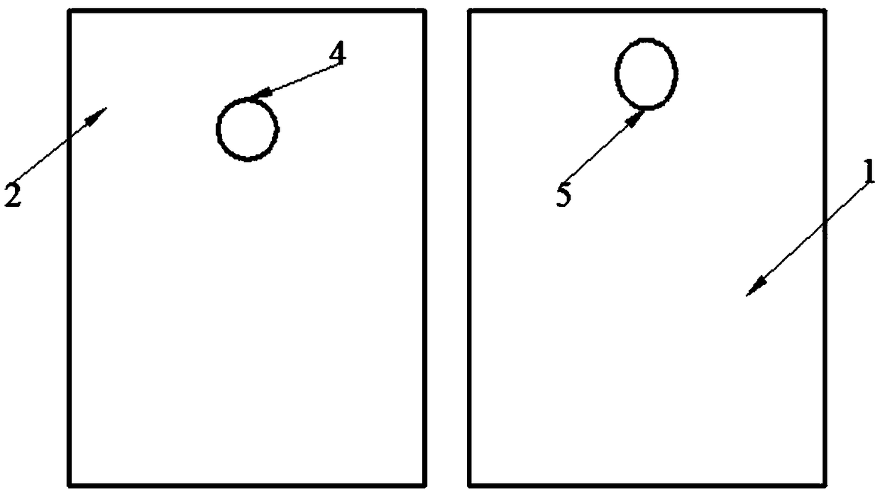
[0026] figure 1 Schematic diagram of the elastic deformation of a weakly rigid part subjected to laser shock. figure 2 It is a schematic diagram of the comparison of the spot shape of the laser beam hitting the thin plate and the deformed thin plate. Among them, 1 is the elastically deformed thin plate, 2 is the thin plate, 3 is the pulsed laser beam, 4 is the light spot on the thin plate, and 5 is the light spot on the deformed thin plate. Such as figure 1 As shown, under the action of the laser shock wave force, the weak stiffness area of ​​the part will undergo elastic deformation. When the deformation hits the target, the laser beam cannot act on the part perpendicularly, which will cause the spot shape to change when the laser beam hits the thin plate. , at the same time the position of the laser action has shifted, such as figure 2 shown. This makes the laser energy distribution, overlapping rate, etc. inconsistent with the set parameters, and the area where the la...


PUM

PropertyMeasurementUnit
strengthaaaaaaaaaa

Abstract

The invention belongs to the technical field of laser shock strengthening, and discloses a method for improving laser shock precision and efficiency of weak rigidity parts. The method comprises the steps that the rigidity of the weak rigidity parts is analyzed by UG three-dimensional software, and shock regions with different rigidity are obtained; laser shock parameters are set, laser with smaller power density is used in the area with weaker rigidity, and laser with larger power density is used in the area with larger rigidity; the depth and strength of residual compressive stress can meet the requirements by adjusting pulse width and increasing shock times; and a sensor is used to monitor the elastic deformation of the weak rigidity parts during processing, and parameters controlling and deformation monitoring are repeated so as to finally improve the laser shock precision and efficiency of the weak rigidity parts. According to the method for improving the laser shock precision andefficiency of the weak rigidity parts, the laser shock is carried out on different rigidity regions of parts by changing the laser parameters in real time, so that the elastic deformation degree is reduced, and the elastic deformation recovery time is shortened; and shocking parts under the condition of excessive elastic deformation which causes spot shape change and action position deviation to affect processing precision and strengthening effect is avoided.

Description

technical field [0001] The invention belongs to the technical field of laser shock strengthening, and more specifically relates to a method for improving the accuracy and efficiency of laser shocking of parts with weak stiffness. Background technique [0002] Laser shock peening is a technology that uses the strong shock waves generated by the interaction between short pulse width laser beams and substances to modify materials and improve the properties of materials such as fatigue resistance, wear resistance and corrosion resistance. As a new type of surface treatment technology, the effect of laser shock strengthening has been verified in the fields of aviation, aerospace, biomedicine, energy, etc., and is gradually becoming mature. [0003] With the development of industrialization in our country, the requirements for parts are getting higher and higher, and the parts are becoming more integrated, complex and lightweight. High-precision weak stiffness parts are widely us...

Claims


Application Information

Patent Timeline
Patent Type & Authority Applications(China)
IPC IPC(8): C21D10/00C21D11/00
CPCC21D10/005C21D11/00
Inventor 张永康杨丰槐林超辉
Owner GUANGDONG UNIV OF TECH
Why Eureka
Try Eureka