Shock damper and method for setting the shock damper

A technology of shock absorbing device and shock absorbing unit, which is applied in the direction of spring/shock absorber, mechanical equipment, inertial effect shock absorber, etc., can solve the problems of difficult design and lack of wide applicability, and achieve stable shock absorbing performance Effect

Inactive Publication Date: 2007-06-27
ADVANCED SYST
View PDF6 Cites 2 Cited by
  • Summary
  • Abstract
  • Description
  • Claims
  • Application Information

AI Technical Summary

Problems solved by technology

In this way, the external dimensions of the shock absorbing device are limited by the length of the rails, and it is not easy to design the external dimensions smaller than the rail lengths of the two rails, which lacks wide applicability.

Method used


Image

  • Shock damper and method for setting the shock damper
  • Shock damper and method for setting the shock damper
  • Shock damper and method for setting the shock damper

Examples


Embodiment 1

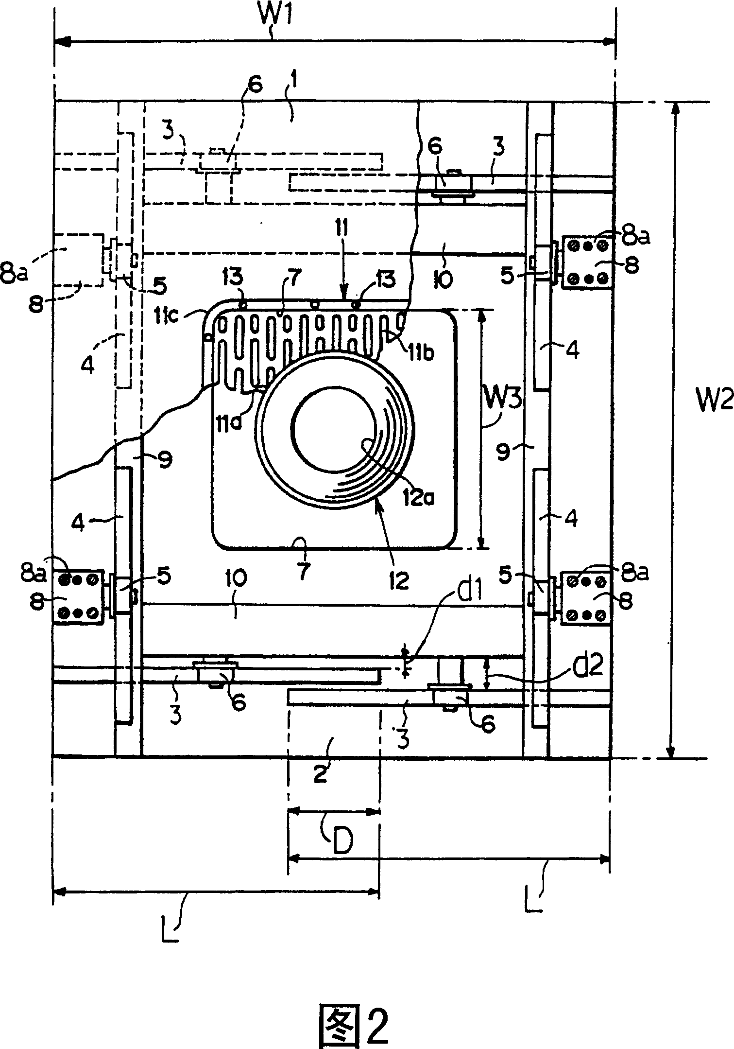
[0116] In Fig. 2 and Fig. 6, the upper platform 1 and the lower platform 2 are formed into a rectangle, and their external dimensions are W2=about 900mm, and W1=about 700mm. The first rail 3 has a rail length L=approximately 400 mm, and is arranged on the lower frame 2 .

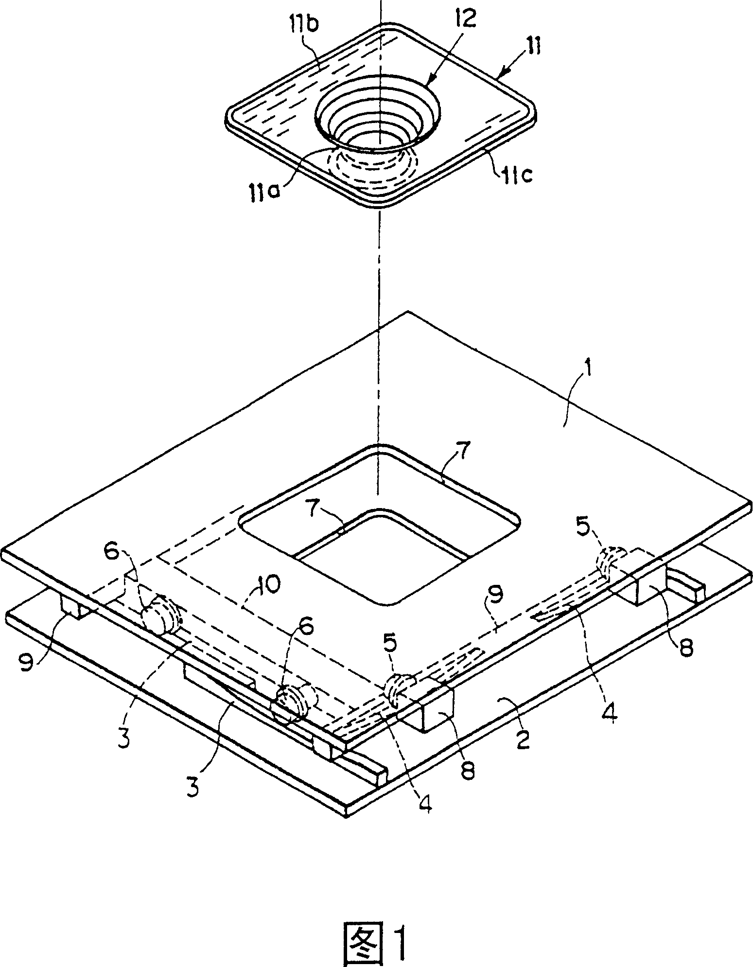
[0117] As shown in the present invention, the track frame 9 and the roller frame 10 assembled into a well shape are movably arranged between the upper platform 1 and the lower platform 2, and the opening 7 is opened by the track frame 9 and the roller frame 10. The maximum dimension of W3=approximately 450nm, such a large-sized opening 7 can make the wiring of cables passing through the opening 7 not affect the damping performance.

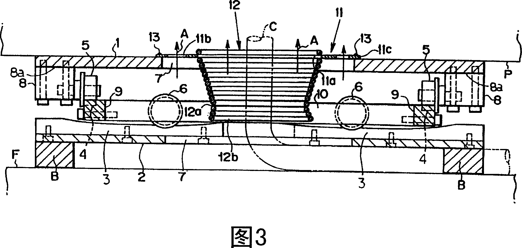
[0118] In addition, the space formed between the upper platform 1 and the lower platform 2 has a height of about 80 mm. When a server rack (shock-absorbing object P) with a normal size and height of 2000 mm is fixed on the upper platform 1, the distance from the ground F The se...

Embodiment 2

[0196] The external dimensions of each upper frame 1 and lower frame 2 of the shock absorbing units 111, 112 are that the upper frame 1 is a rectangle with W12 = about 400 mm and a longitudinal dimension W11 of about 890 mm. The lower frame 2 is a rectangle with W14 = about 300 mm and a longitudinal dimension W11 of about 890 mm. The first rail 3 has a rail length of about 400 mm and is arranged on the upper frame 1 .

[0197] Damping units 111 and 112 of this structure are installed in the same manner as the installation method in FIG. 20 . The shock-absorbing object P has a square box shape with an outer dimension of about 700 mm, and a wiring device C extending from the ground F is connected to the lower surface side of the shock-absorbing object P.

[0198] Make the approximate center of the upper frame 1 of the shock-absorbing units 111,112, after being positioned at the end of the shock-absorbing object P, use the connecting parts 121,122 of about 1100mm in length to co...


PUM


Abstract

A base isolation device and a method of installing the base isolation device capable of developing a stable base isolation performance for a base-isolated object having wiring equipment connected thereto and allowing the base isolation device to be installed on an existing base-isolated object without stopping the operation of the base-isolated object, wherein vertically curved rails and rollers running on the rails are disposed between an upper frame and a lower frame orthogonal to each other in a horizontal plane whereby vibration can be damped, and an opening part or an insert area for inserting, therein, the wiring equipment connected to the base-isolated object is provided whereby , at the time of earthquake, the wiring equipment does not touch the base isolation device, and the stable base isolation performance can be developed.

Description

technical field [0001] The invention relates to a shock absorbing device and a setting method of the shock absorbing device. Background technique [0002] Japanese Patent Laid-Open No. 2000-14472 discloses a shock absorber. In this damping device, between the upper base plate fixed on the damping object and the lower base plate fixed on the ground, the rails curved in the vertical direction are arranged in a well shape at an angle of about 90 degrees, and the rails that roll on the rails are arranged in a well shape. roll. [0003] In this conventional damping device, the roller rises on the rail due to the vibration in the left and right directions, and after absorbing the vibration in the left and right direction, the roller descends on the rail under its own weight (the load of the damping object, etc.). Vibration (earthquake, etc.) is absorbed and attenuated by the vertical movement and displacement of the roller. [0004] However, when the shock-absorbing object is a...

Claims


Application Information

Patent Timeline
Patent Type & Authority Patents(China)
IPC IPC(8): F16F15/02E04H9/02F16F7/10F16F15/04
CPCF16F15/02E04H9/023F16F15/04F16F7/10F16F15/021A47B97/00
Inventor 川岛满次中村彻人菊池巧河野保田野信夫
Owner ADVANCED SYST
Why Eureka
Try Eureka