Isolated voltage regulator with one core structure

A technology of voltage regulator and magnetic device, applied in the direction of regulating electric variable, control/regulating system, output power conversion device, etc., can solve the problems of complex control and so on

Active Publication Date: 2007-07-04
DELTA ELECTRONICS INC
View PDF3 Cites 2 Cited by
  • Summary
  • Abstract
  • Description
  • Claims
  • Application Information

AI Technical Summary

Problems solved by technology

Because it needs to use two controllers, its control is also more complicated
Overall, this solution increases the cost, profile and manufacturing complexity of the voltage regulator components

Method used


Image

  • Isolated voltage regulator with one core structure
  • Isolated voltage regulator with one core structure
  • Isolated voltage regulator with one core structure

Examples


Embodiment Construction

[0024] While the present invention is capable of many different forms of embodiments, a preferred embodiment is described and illustrated in detail below. The description is intended to illustrate the principles of the invention and should not be construed as limiting the broad concepts of the invention to the specific specific embodiments described above.

[0025] Please refer to FIG. 4, which shows the solution of the present invention with a simple circuit, low profile and low cost. In this topology, the number of interleaved channels is at least two, and the phase difference between each adjacent interleaved channel is a quotient obtained by dividing 360 degrees by the number of interleaved channels.

[0026] Figure 5 is a diagram showing a basic unit used in the topology of the present invention. The -DC voltage Vin at an input capacitor 510 is connected to a switch 511 and via a rectifier circuit 502 to the output lead. In rectifier circuit 502 , transformer 513 is integ...


PUM


Abstract

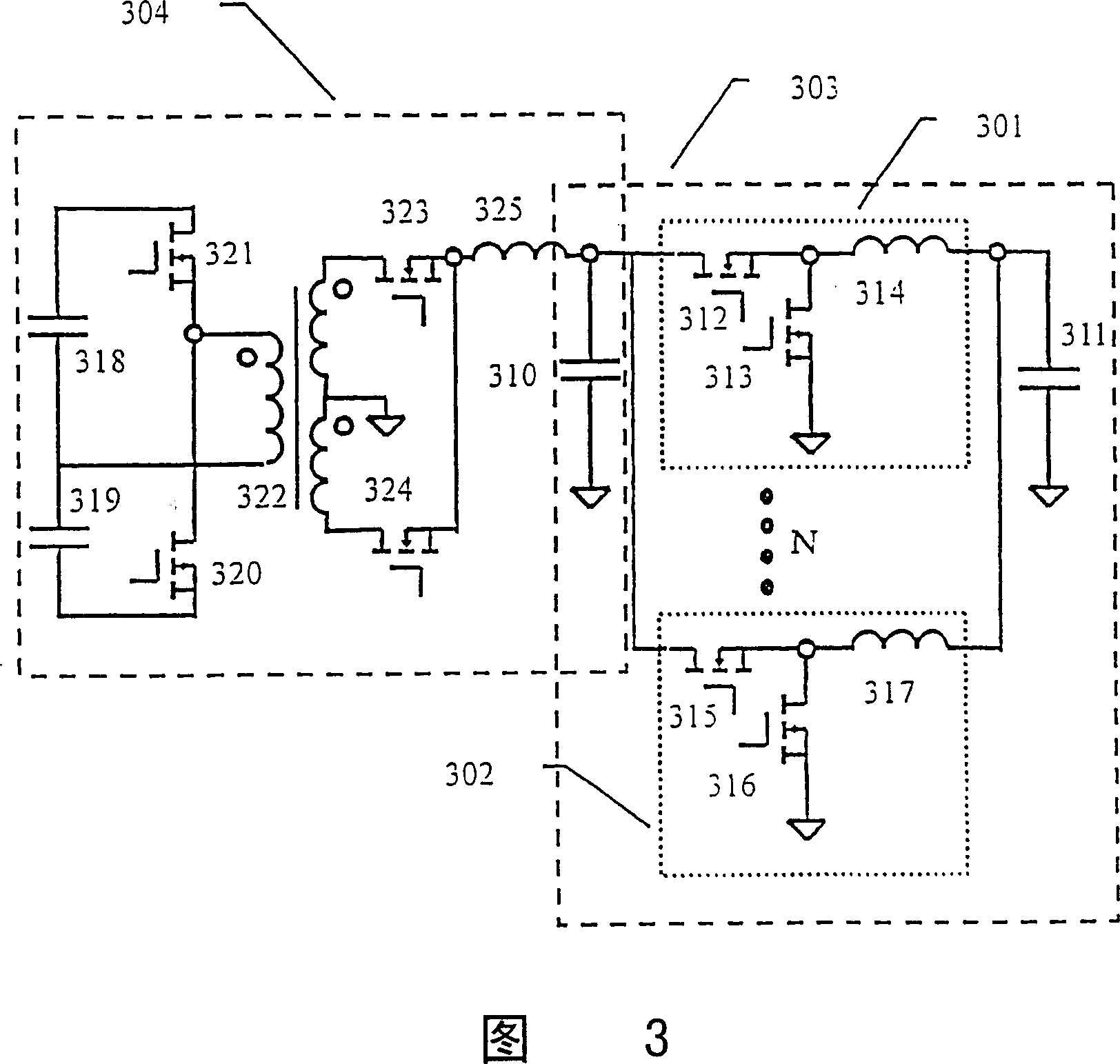
The present invention proposes a new structure for a high input VRM. In this present invention, the interleaved voltage regulator is provided. The interleaved voltage regulator includes an integrated magnetic device for performing both transformer and output choke filter function, a first switch, a second switch, a third switch, and a fourth switch, wherein the integrated magnetic device includes a transformer having a first primary winding, a second primary winding, a first secondary winding, and a second secondary winding, a first choke filter having one end coupled to a first terminal of the first secondary winding, and a second choke filter having one end coupled to a first terminal of the second secondary winding, and the other end of the second choke filter coupled to the other end of the first choke filter to form the output terminal of the isolated voltage regulator. The first switch, the second switch, the first choke filter, and the first secondary winding form a synchronous rectifier circuit. The third switch, the fourth switch, the second choke filter, and the second secondary winding form another synchronous rectifier circuit.

Description

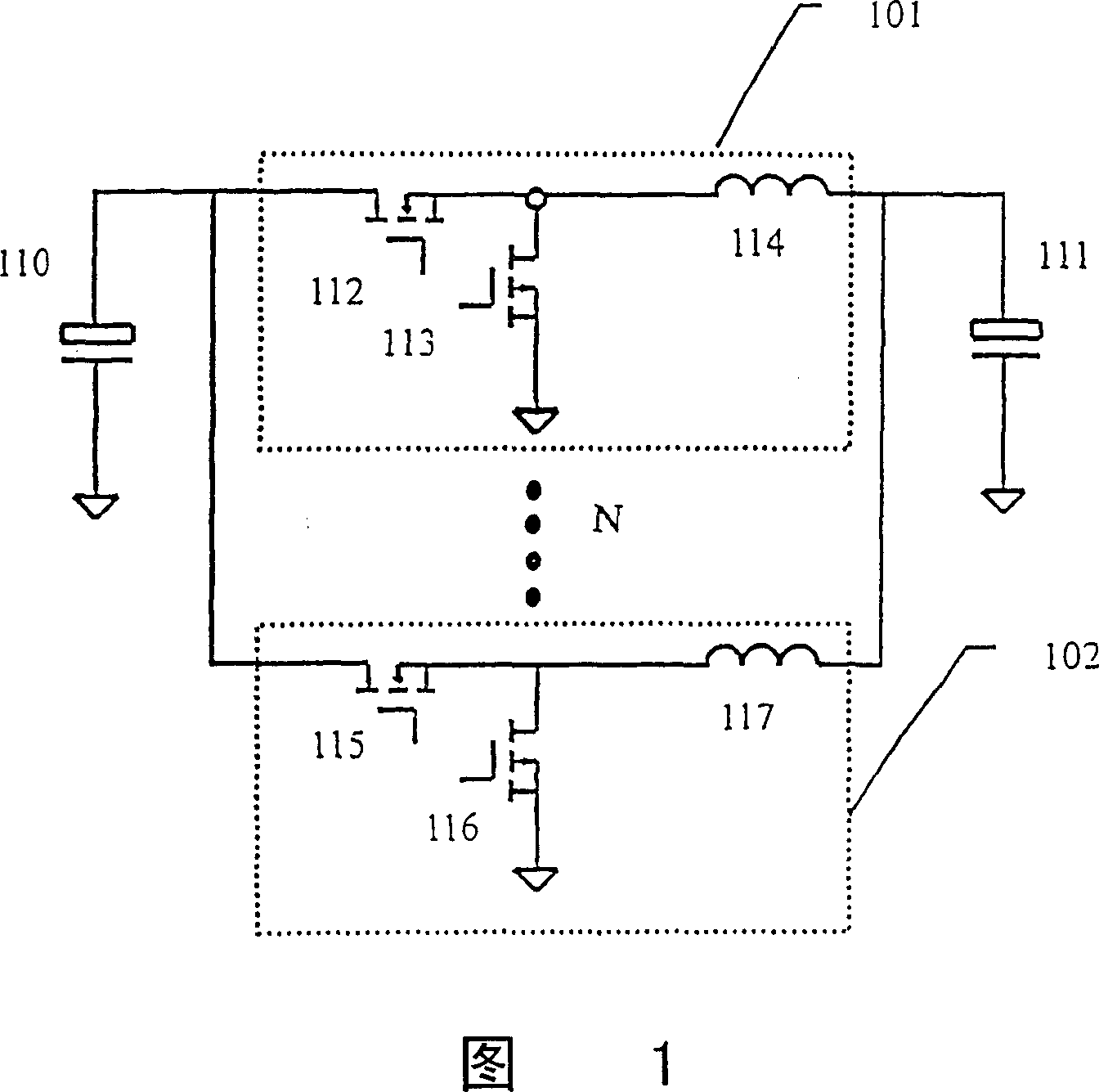
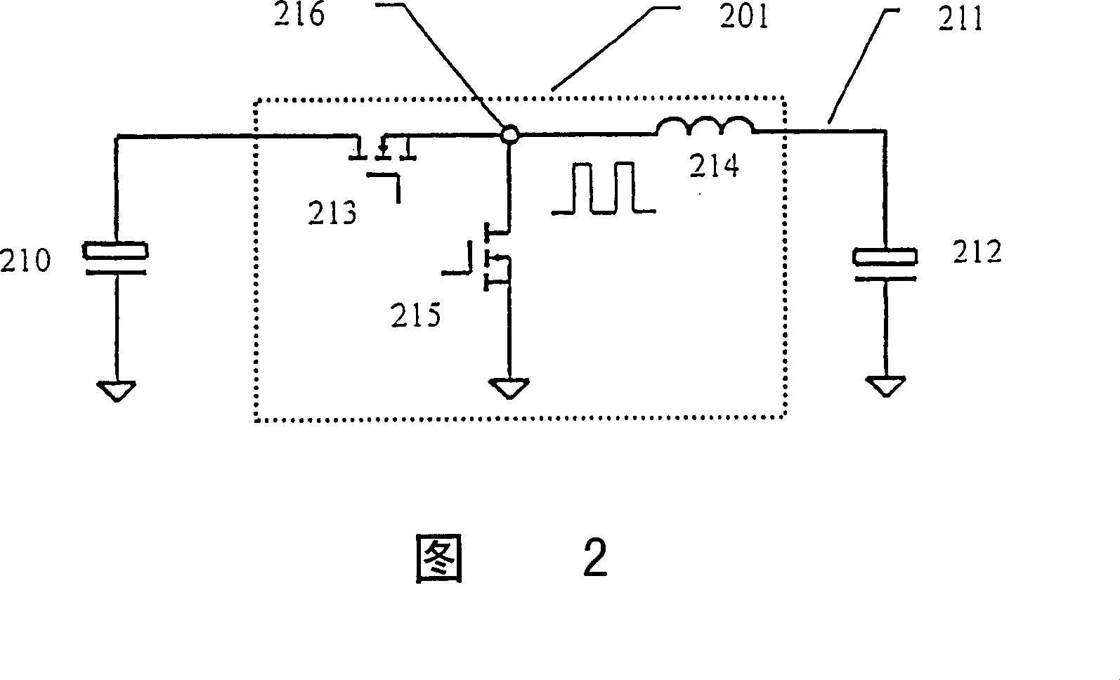
technical field [0001] The invention relates to a voltage regulator providing low voltage and high current for a processor or a memory, in particular to an isolated high input voltage regulator with an integral magnetic device. Background technique [0002] Modern processors operate at a very low voltage and a high current to meet faster and more efficient data processing requirements. A voltage regulator module (Voltage Regulator Module, VRM) is used to provide power to the microprocessor. [0003] Please refer to FIG. 1 , which is an interleaved synchronous buck topology with at least two interleaved channels, which is widely used in 5V / 12V input voltage regulator components. The phase difference between each adjacent interleaved channel is the quotient obtained by dividing 360 degrees by the number of interleaved channels. [0004] FIG. 2 shows a basic unit of the interleaved synchronous buck converter shown in FIG. 1 . A DC voltage input terminal Vin of an input capac...

Claims


Application Information

Patent Timeline
Patent Type & Authority Patents(China)
IPC IPC(8): H02M3/28H02M1/14G05F1/46H02M3/335
CPCY02B70/1475H02M3/33592Y02B70/10
Inventor 李文华柯忠伟黄贵松章进法
Owner DELTA ELECTRONICS INC
Why Eureka
Try Eureka