LCD backlighting inverter circuit and LCD

A liquid crystal display and inverter technology, which is applied in the field of liquid crystal display backlight inverter circuits, can solve problems such as limiting current startup characteristics, limiting dimming range, etc.

Inactive Publication Date: 2008-04-09
KONINKLIJKE PHILIPS ELECTRONICS NV
View PDF4 Cites 0 Cited by
  • Summary
  • Abstract
  • Description
  • Claims
  • Application Information

AI Technical Summary

Problems solved by technology

However, the usually high inductance of L1 limits the current start-up characteristics and limits the dimming range

Method used


Image

  • LCD backlighting inverter circuit and LCD
  • LCD backlighting inverter circuit and LCD
  • LCD backlighting inverter circuit and LCD

Examples


Embodiment Construction

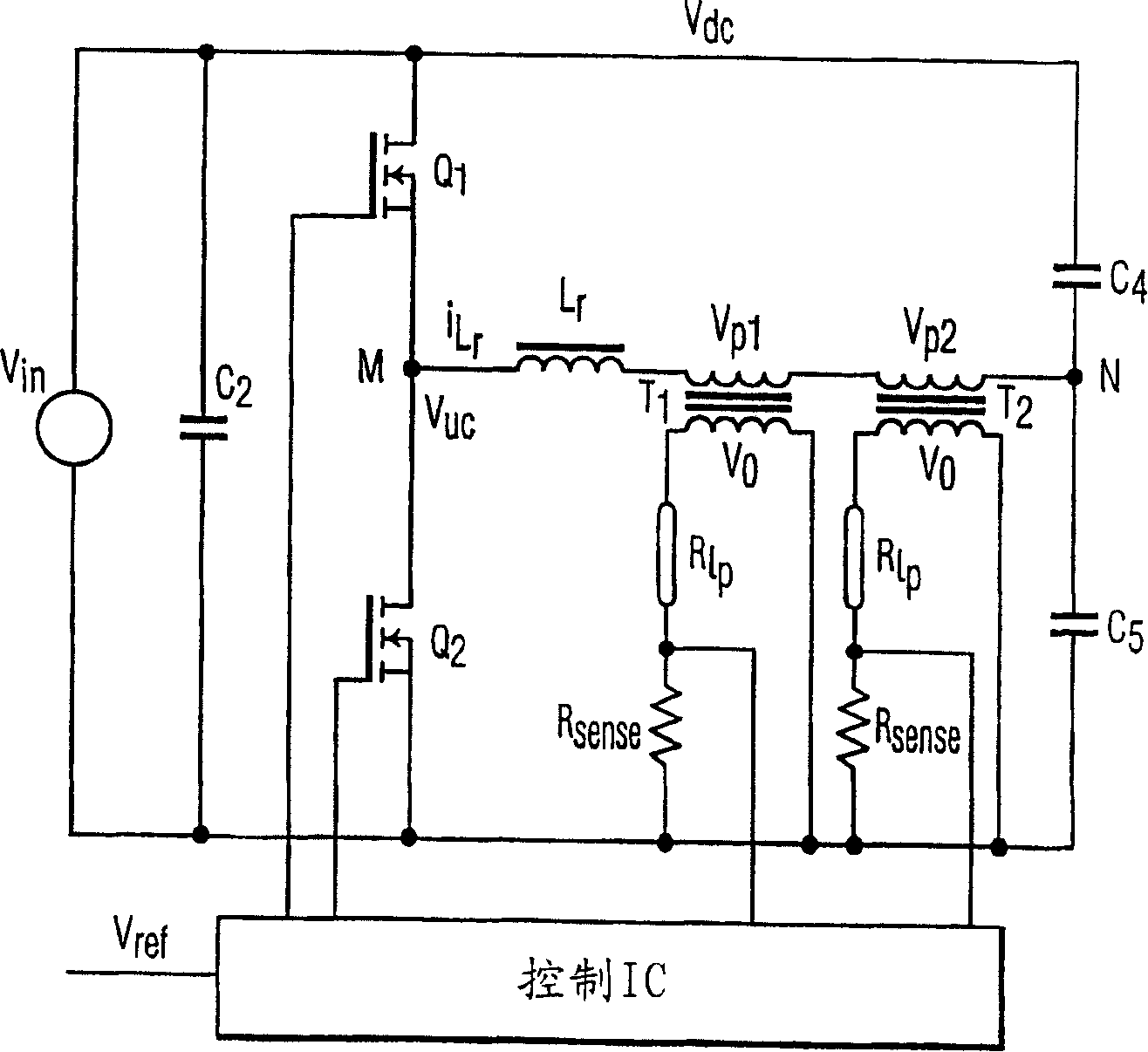
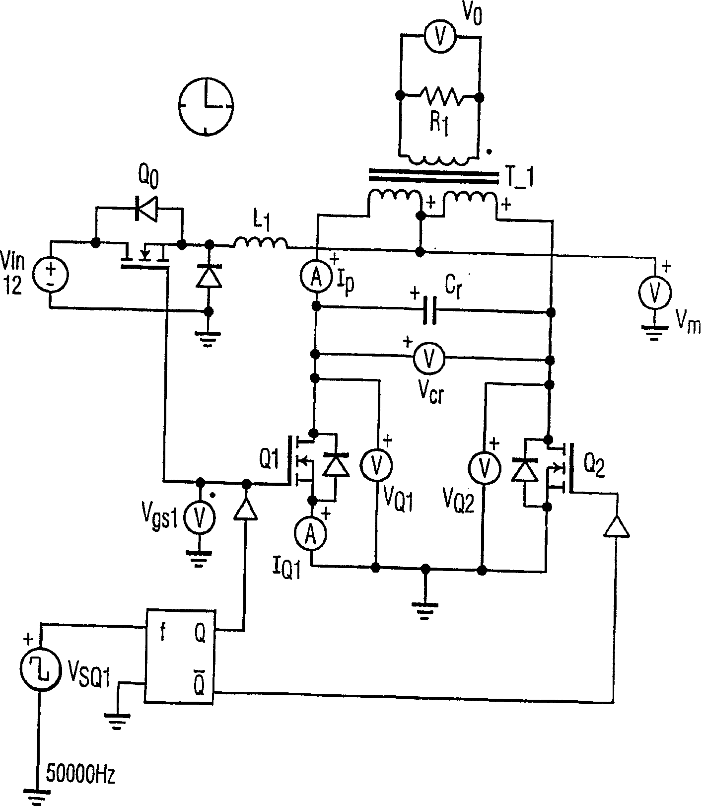
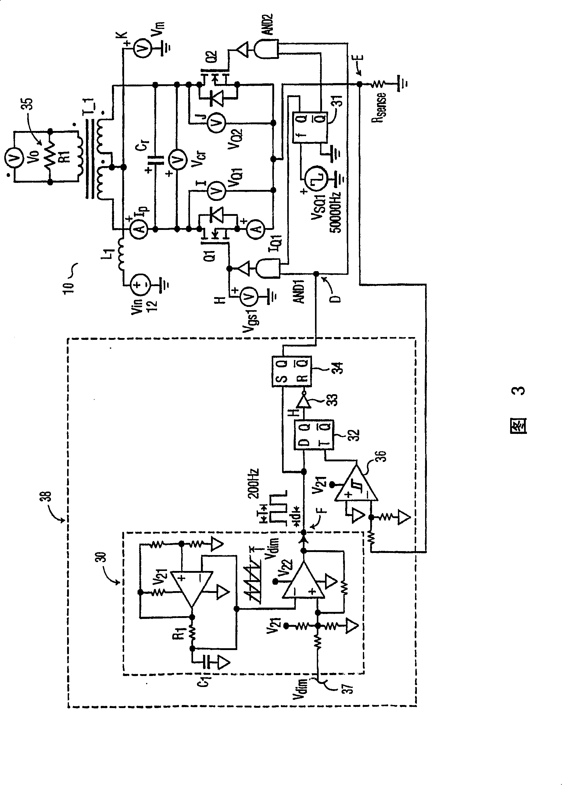
[0016] Returning now to the drawings, in which like reference numerals indicate like or identical elements throughout the several schematic diagrams, FIG. 3 illustrates an electronic liquid crystal display backlight inverter circuit 10 in accordance with an embodiment of the present invention. It is foreseeable that the improved circuit according to the present invention will be used in liquid crystal display backlighting applications.

[0017] The LCD backlight inverter circuit 10 according to the present invention is a voltage-fed push-pull resonant circuit for the operation of the load 35 . The load 35 shown in Figure 3 is of the resistive type, but the load could be, but is not limited to, a cold cathode type fluorescent lamp (eg CCFL). For example, light from load 35 may be used to illuminate a computer's liquid crystal display flat panel display (not shown). The LCD backlight inverter circuit 10 may be powered by a conventional AC power source, which is then rectified a...


PUM


Abstract

An improved electronic LCD backlighting inverter circuit for high frequency operation under low frequency pulse width modulation (PWM) for dimming control. The improved electronic LCD backlighting inverter is based on a voltage-fed push-pull LLC resonant inverter circuit configuration including a resonant inductor (L), magnetizing inductance of an output transformer (L), and resonant capacitor (C). For large values of magnetizing inductance the LLC circuit effectively becomes an LC resonant circuit. By synchronizing the high frequency switching signal and the low frequency modulation frequency using logic control circuitry, a wide dimming range and higher efficiency are achieved under PWM control.

Description

technical field [0001] In general, the present invention relates to a liquid crystal display backlight inverter circuit suitable for liquid crystal display backlight or similar applications, and more particularly to a high efficiency, small size, and wide dimming range liquid crystal display backlight inverter circuit. Background technique [0002] Liquid crystal display backlight applications require efficient, small-sized backlights for information display. Narrow diameter cold cathode fluorescent lamps (CCFLs), such as the T1 type, are widely used in such industrial applications. To drive these CCFLs, an electronic LCD backlight inverter circuit with high efficiency, small size, and wide dimming range is required. Currently, half-bridge resonant converter circuits using voltage feeding, such as figure 1 , and a current-fed push-pull resonant converter circuit such as figure 2 Shown, to drive CCFL and other fluorescent lamps. Although widely used, these circuits have ...

Claims


Application Information

Patent Timeline
Patent Type & Authority Patents(China)
IPC IPC(8): H05B41/392H05B41/24H05B41/282
CPCH05B41/2824H05B41/3927
Inventor 张劲
Owner KONINKLIJKE PHILIPS ELECTRONICS NV
Why Eureka
Try Eureka