Supercharge Your Innovation With Domain-Expert AI Agents!

Pressure reducing valve with gauge embedded handle

A technology of gauges and pressure reducing valves, applied in the direction of measuring fluid pressure, measuring fluid pressure through mechanical components, instruments, etc., can solve the problem of not being able to take out the pressure gauge cover

Active Publication Date: 2007-07-11
SMC CORP
View PDF8 Cites 0 Cited by
  • Summary
  • Abstract
  • Description
  • Claims
  • Application Information

AI Technical Summary

Problems solved by technology

Also, since the pressure gauge cover is installed in the handle in a state fixed to the pressure gauge, the pressure gauge cover cannot be taken out in the installed state

Method used


Image

  • Pressure reducing valve with gauge embedded handle
  • Pressure reducing valve with gauge embedded handle
  • Pressure reducing valve with gauge embedded handle

Examples


Embodiment Construction

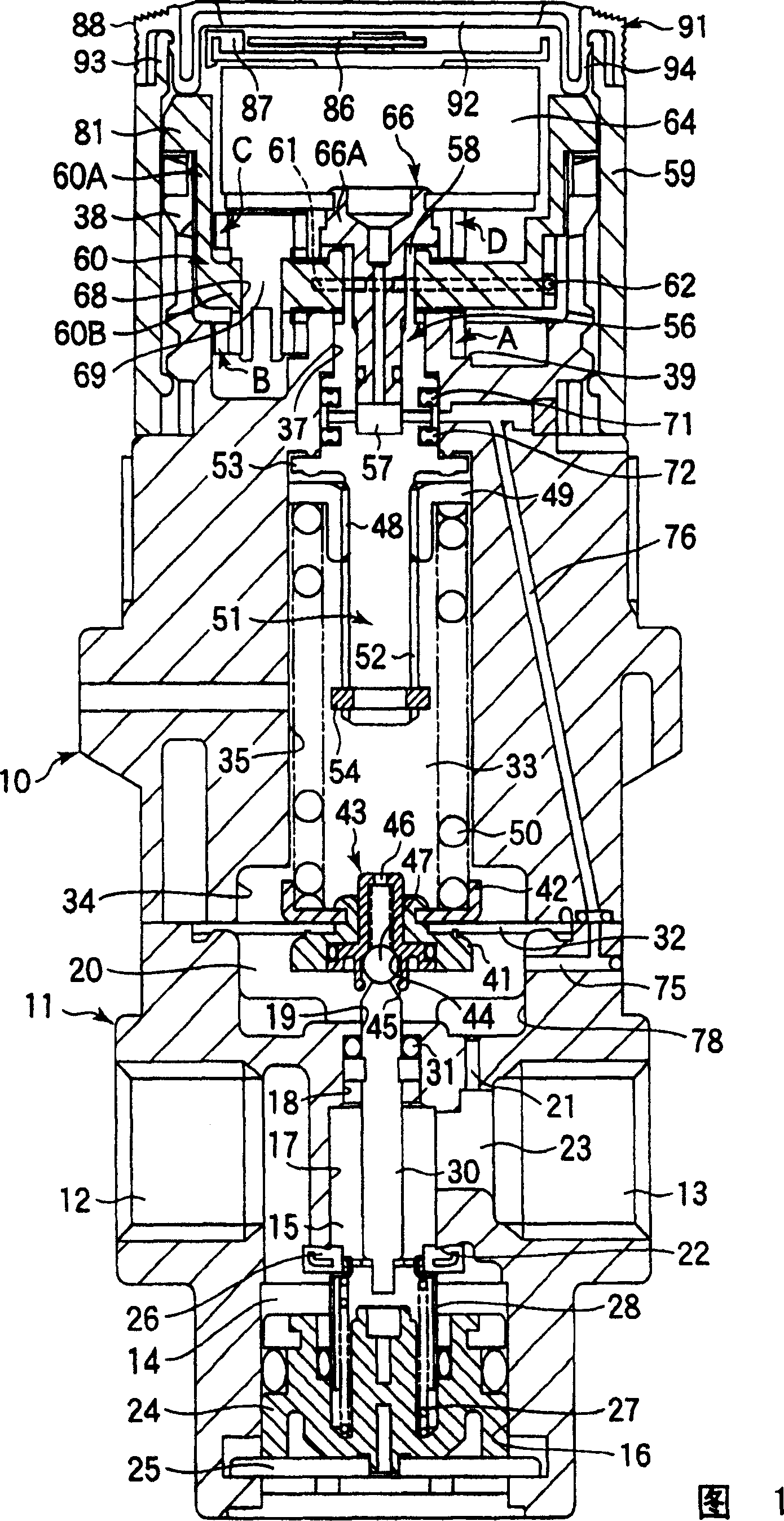
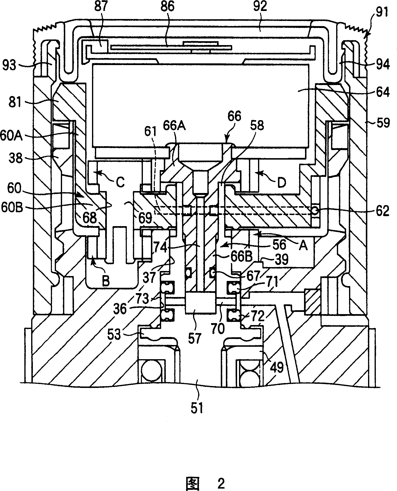
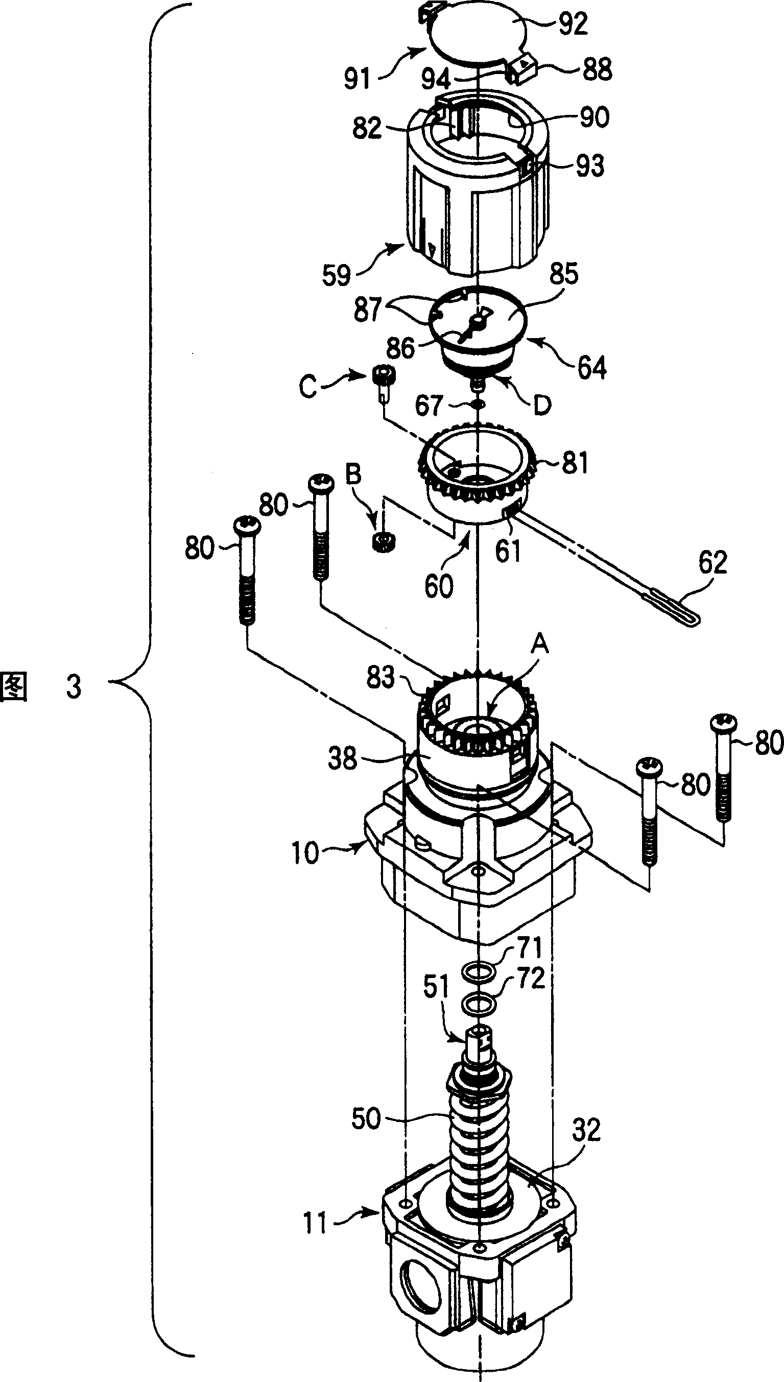
[0021] Figures 1 to 4 show the embodiment of the handle-type pressure reducing valve with gauge of the present invention. In the description of FIGS. 1 to 3 , the term “upper and lower” was used, but if the position of the pressure reducing valve changes, it is conceivable to modify the upper and lower according to the change of its position.

[0022] The valve body is composed of a metal or synthetic resin valve body 11 and a valve cover 10 .

[0023]A primary side port 12 and a secondary side port 13 are formed on the side of the valve body 11, and a valve chamber (primary pressure chamber) 14 and a secondary pressure chamber 15 are formed between the primary side port 12 and the secondary side port 13. . In the central portion of the valve main body 11, a large-diameter hole 16, a middle-diameter hole 17, a small-diameter hole 18, an insertion hole 19, and a feedback chamber hole 78 are sequentially formed from below. Chamber 14 communicates with primary side port 12 . A...


PUM


Abstract

The present invention provides a gauge handle type relief valve of which the relative rotation of pressure gauge and valve body is almost deprived of, wherein a gear (D) is fixed to a pressure gauge guide (66) connected to a pressure gauge (64), a gear (A) being coaxial with the gear (D) is fixed to the valve bodies (10, 11). A support shaft (69) is rotatably inserted through the through hole (68) which is located at non-center position of the bottom of pressure-regulating guide (60), a gear (C) and a gear (D) fixed to the both ends of support shaft (69) are engaged with the gear (B) and gear (A), thereby the pressure gauge (64) is not allowed to rotate relative to the valve bodies (10, 11) when the handle is rotated.

Description

technical field [0001] The present invention relates to a pressure reducing valve with a gauge handle, which sets a secondary side fluid pressure by operating a handle having a cylindrical portion, and a pressure gauge is provided in the handle. Background technique [0002] In the past technology 1 (JP 4-45043 publication) and the past technology 2 (JP-A 2001-5534 publication), it is described that such a handle-type pressure reducing valve with a meter: the primary side port (supply port) and A valve chamber is arranged between the secondary side ports (output ports), and the main valve body (supply valve body) in the valve chamber is urged toward the direction close to the main valve seat (supply valve seat) by the valve spring (return spring). The body is installed between the feedback part (diaphragm) and the pressure regulating spring holder to exert force in the direction away from the main valve seat. A pressure gauge is arranged in the handle with a cylindrical part...

Claims


Application Information

Patent Timeline
Patent Type & Authority Patents(China)
IPC IPC(8): F16K17/04G05D16/14F16K37/00G05D16/06F16K31/14G01L7/00G01L7/16
CPCG01L7/166B25B19/00
Inventor 伊藤石典
Owner SMC CORP
Features
  • R&D
  • Intellectual Property
  • Life Sciences
  • Materials
  • Tech Scout
  • Unparalleled Data Quality
  • Higher Quality Content
  • 60% Fewer Hallucinations
Learn More