
Electromagnetic actuator

An actuator, electromagnetic technology, applied in the direction of the fluid using vibration, can solve the problems of inconvenient assembly, the electromagnetic actuator cannot adjust the resonance frequency, etc., and achieve the effects of simple operation, simple structure and large vibration amount.

Inactive Publication Date: 2007-07-25
SHICOH MOTOR (SHANGHAI) CO LTD
View PDF7 Cites 0 Cited by
  • Summary
  • Abstract
  • Description
  • Claims
  • Application Information

AI Technical Summary

Problems solved by technology

[0006] The purpose of the present invention is to solve the shortcomings of existing electromagnetic actuators that cannot adjust the resonant frequency and inconvenient assembly, so as to provide an electromagnetic actuator that can adjust the resonant frequency, which not only has a reasonable structure, but also can Adjusting the resonance frequency can be automatically welded on the printed substrate in the automatic production line, thereby improving production efficiency

Method used


Image

  • Electromagnetic actuator
  • Electromagnetic actuator
  • Electromagnetic actuator

Examples


Embodiment Construction

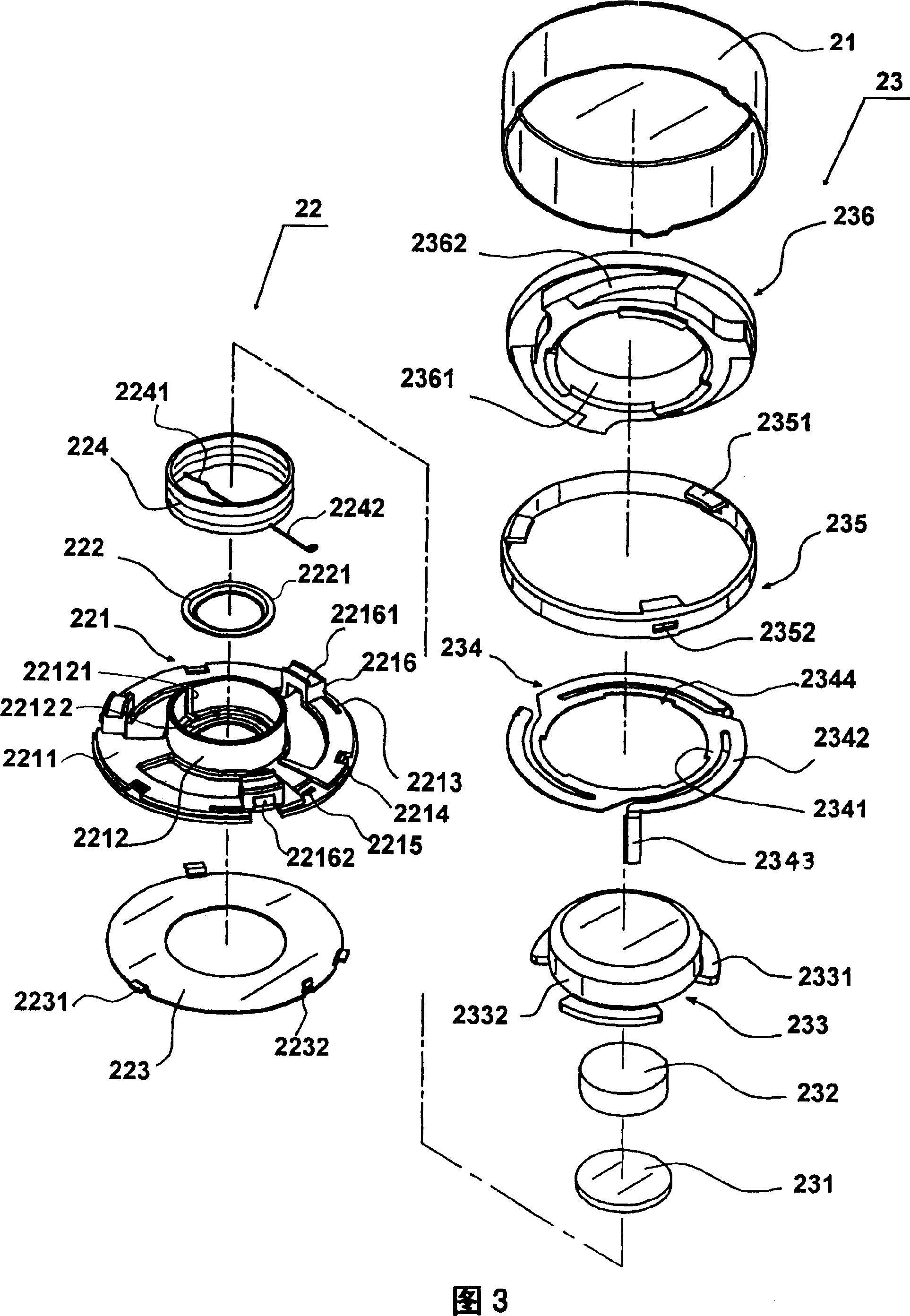
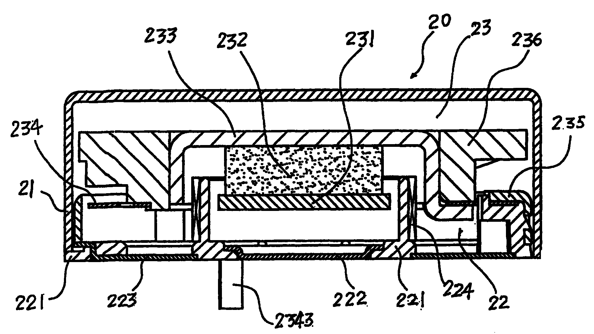
[0028] Please refer to Fig. 2 and Fig. 3, which are the overall and disassembled structural schematic diagrams of the electromagnetic actuator of the present invention. The electromagnetic actuator of the present invention is a device arranged in the mobile phone to notify the carrier of the calling signal of the mobile phone through vibration. The electromagnetic actuator of the present invention includes a casing 21 , a coil component 22 arranged in the lower part of the casing 21 , and a vibrating component 23 arranged on the coil component 22 .

[0029] The coil component 22 includes components such as a base 221 , an inner terminal 222 , an outer terminal 223 , and a coil 224 . The base 221 is made of resin material, and the base 221 is composed of a base plate 2211 and a hollow tube 2212 vertically arranged at the central part of the base plate 2211; three grooves for installing spring adjustment rods are arranged around the base plate 2211 of the base 221 2213, the gro...


PUM


Abstract

An electromagnetic actuator for the vibration of mobile telephone is composed of a shell, a coil unit consisting of the base comprising basic plate and hollow tube, internal and external terminals, and coil sleeving around said hollow tube, and a vibration unit consisting of polar piece magnet, spring, resonant frequency regulator, etc.

Description

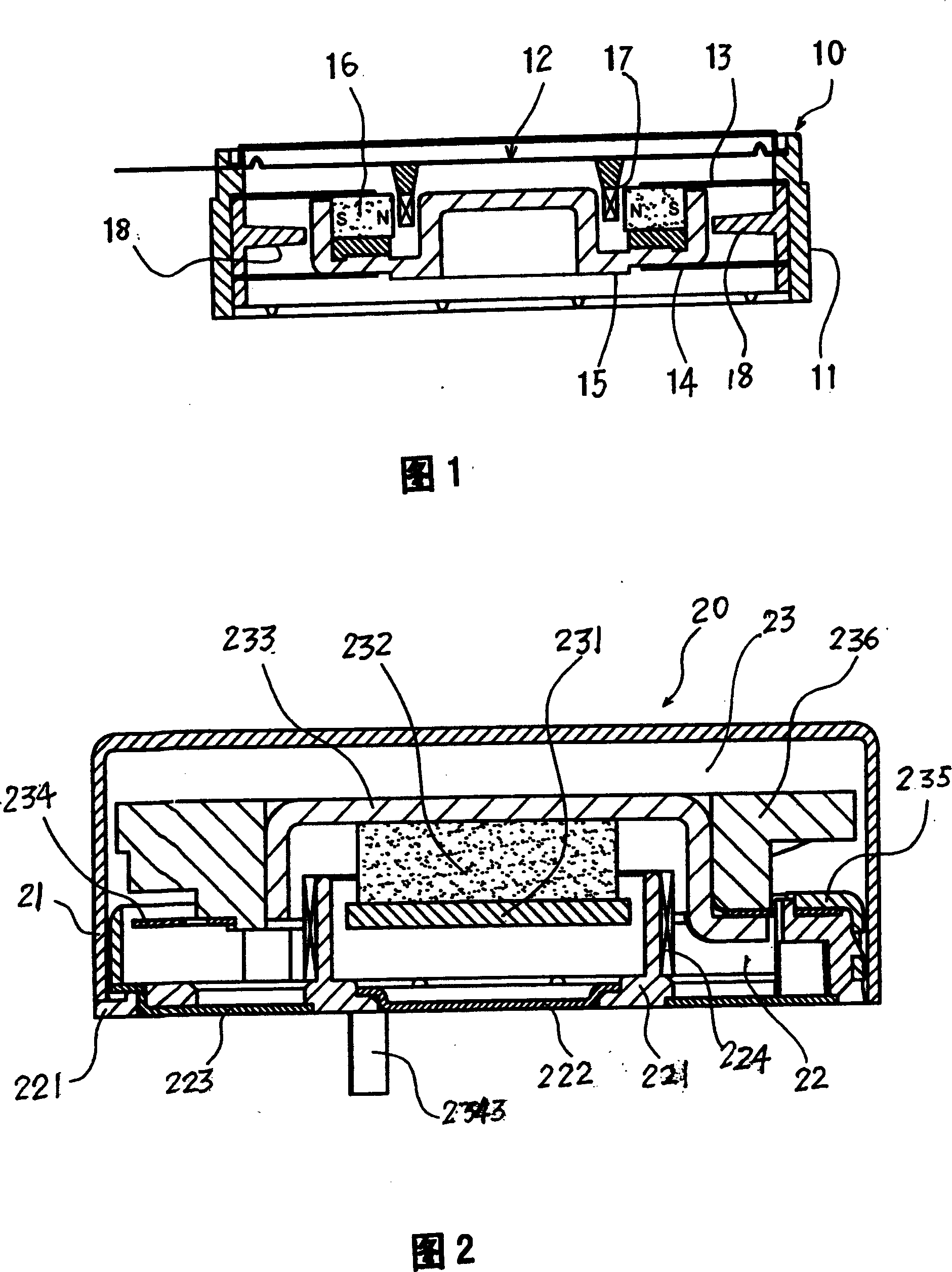
technical field [0001] The invention relates to an actuator, in particular to an electromagnetic actuator which is arranged in a mobile phone and a BP machine, and notifies a user of a call signal of the mobile phone or BP machine through vibration. Background technique [0002] The prior art electromagnetic actuator has been publicly specified in WO99 / 39843. Please refer to FIG. 14. The ring mouth 15, the magnet 16, the coil 17, the flange 18; the vibrating piece 12, the upper vibrating piece 13, and the lower vibrating piece 14 are provided in parallel intervals on the inner wall of the housing 11 from top to bottom; the ring mouth 15 is set on the upper , Between the lower vibrating pieces 13 and 14; the magnet 16 is arranged in the groove of the ring mouth 15; the coil 17 is arranged between the inner wall of the groove of the ring mouth 15 and the magnet 16; A flange 18 is provided. When the actuator is working, by applying low-frequency current to the coil 17, an ele...

Claims


Application Information

Patent Timeline
IPC IPC(8): B06B1/04
Inventor 白木学关口直树陆龙斌
Owner SHICOH MOTOR (SHANGHAI) CO LTD
Learn More