Laminated photoelectric element and making method thereof

A photoelectric element and laminated technology, applied in the direction of electrical elements, photovoltaic power generation, final product manufacturing, etc., can solve the problems of increased junction, low electromotive force of photoelectric elements, and large interface problems, etc., and achieve low short-circuit current and high conversion efficiency effect

Inactive Publication Date: 2007-08-01
CANON KK
View PDF3 Cites 0 Cited by
  • Summary
  • Abstract
  • Description
  • Claims
  • Application Information

AI Technical Summary

Problems solved by technology

However, in the case of stacking a photoelectric element such as a lower photovoltaic element, an intermediate layer, an upper photovoltaic element, and a conductive layer on a substrate, even if the conductive layer 105 that contacts the defective portion 107 of the upper layer can be removed, the The intermediate layer 103 in contact with the defect site 106 of the upper layer cannot be removed
Therefore, since a short-circuit current flows in the defect of the lower layer, the electromotive force of the lower photoelectric element will be lowered.
In particular, since the intermediate layer must maintain a certain layer thickness as a reflective layer, the integrity and series resistance of the semiconductor layers connected to both sides must also be considered, and the resistivity of the material cannot be adjusted at will. Prevents short-circuit current from spreading within the interlayer
In addition, since junctions with intermediate layers composed of different materials occur between multiple photovoltaic elements, characteristic degradation accompanied by FF degradation cannot be avoided.
In addition, when multiple layers are inserted to prevent the shunt resistance from decreasing, the number of junctions will increase, and the problem of the interface will become larger.
[0009] In this way, in order to increase the photocurrent, even if the intermediate layer is introduced as a selective reflection layer, the electromotive force of the photoelectric element is still low.
[0010] In addition, it can be seen that in the structure disclosed in Japanese Patent Laid-Open No. 2001-308354, even if the light reflection and transmission characteristics can be satisfied, in order to have a good connection with the photoelectric element, the photoelectric element will not be damaged when the intermediate layer is formed. impact is not enough

Method used


Image

  • Laminated photoelectric element and making method thereof
  • Laminated photoelectric element and making method thereof
  • Laminated photoelectric element and making method thereof

Examples


Embodiment 1

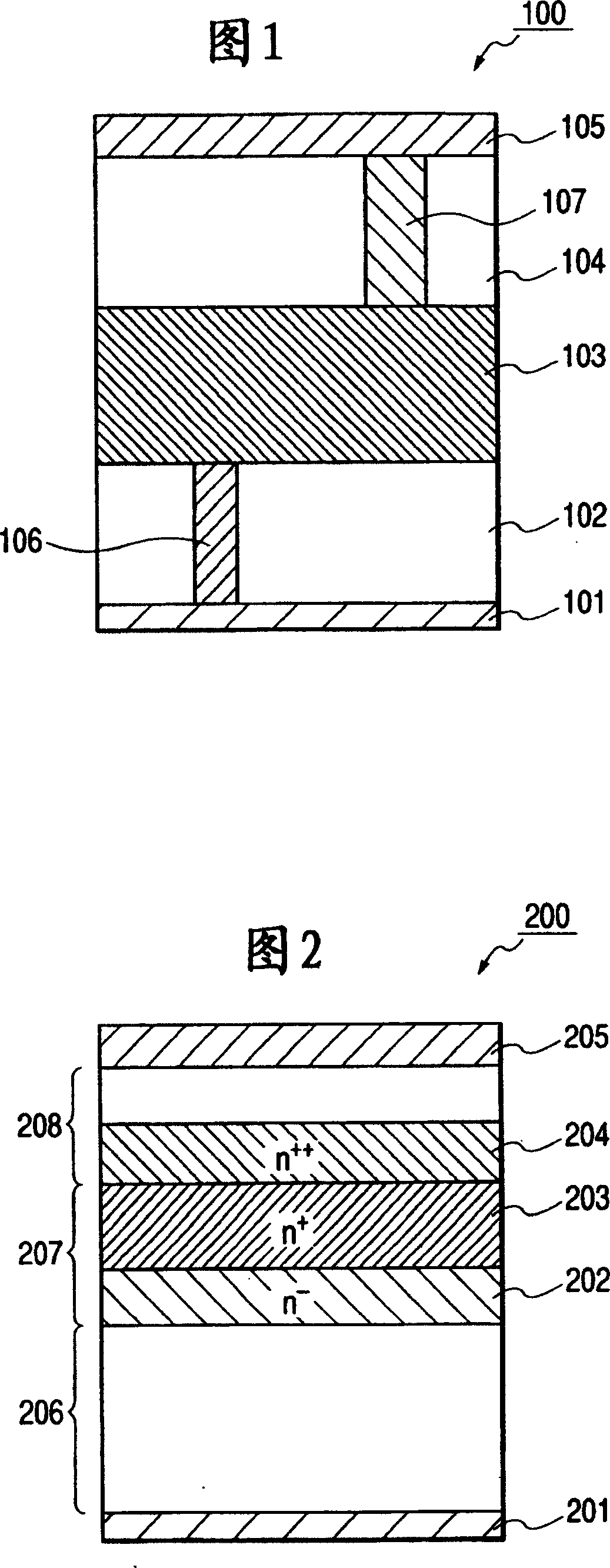
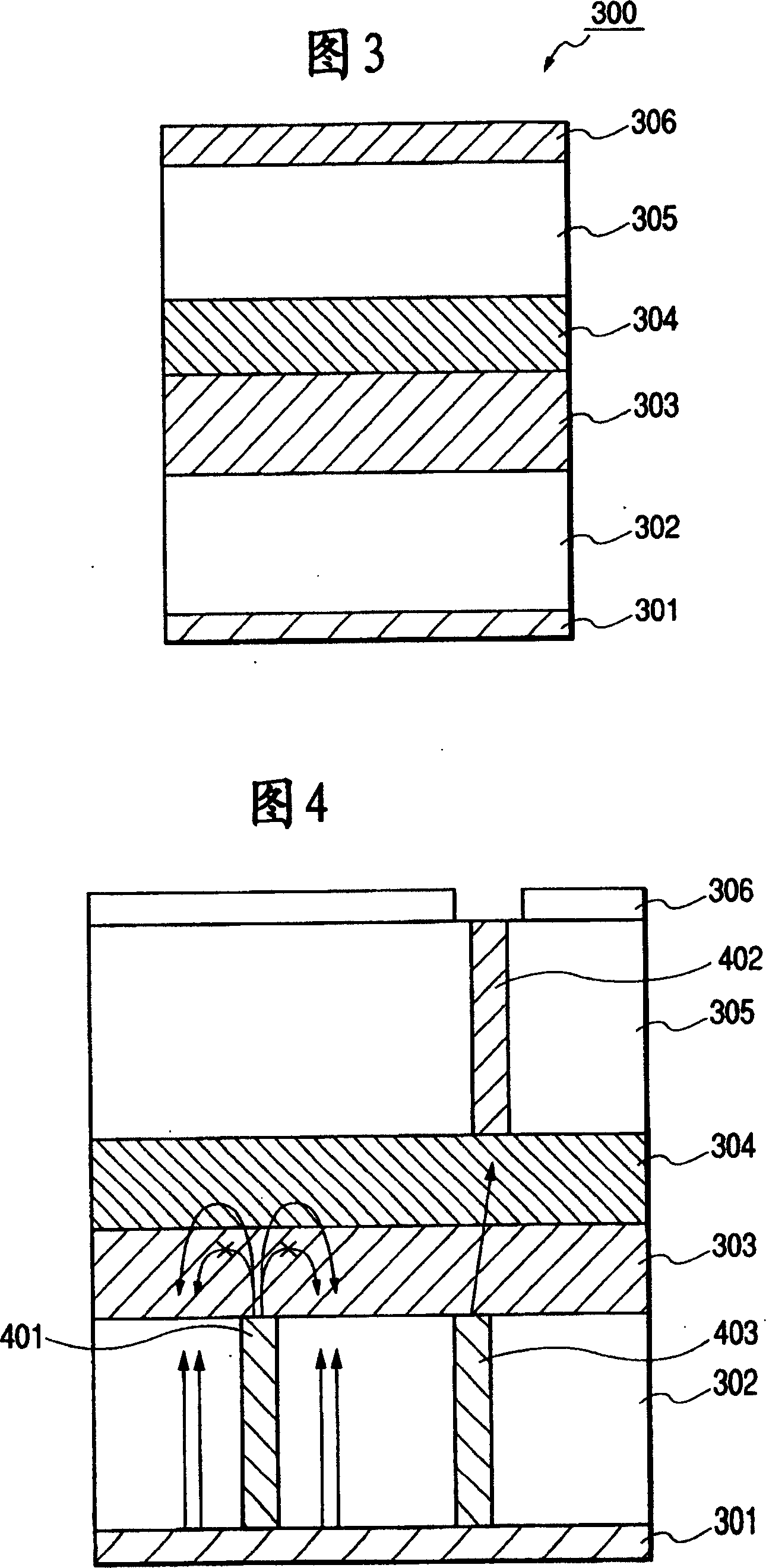
[0099] In this embodiment, a pin-type photoelectric element whose i layer is intrinsic microcrystalline Si is used as the second photoelectric element 302, and a pin-type photoelectric element whose i layer is intrinsic amorphous Si:H is used as the first photoelectric element 305, and An example of the first multi-layer photovoltaic element (see FIG. 3 ) of the present invention was fabricated using zinc oxide as an intermediate layer.

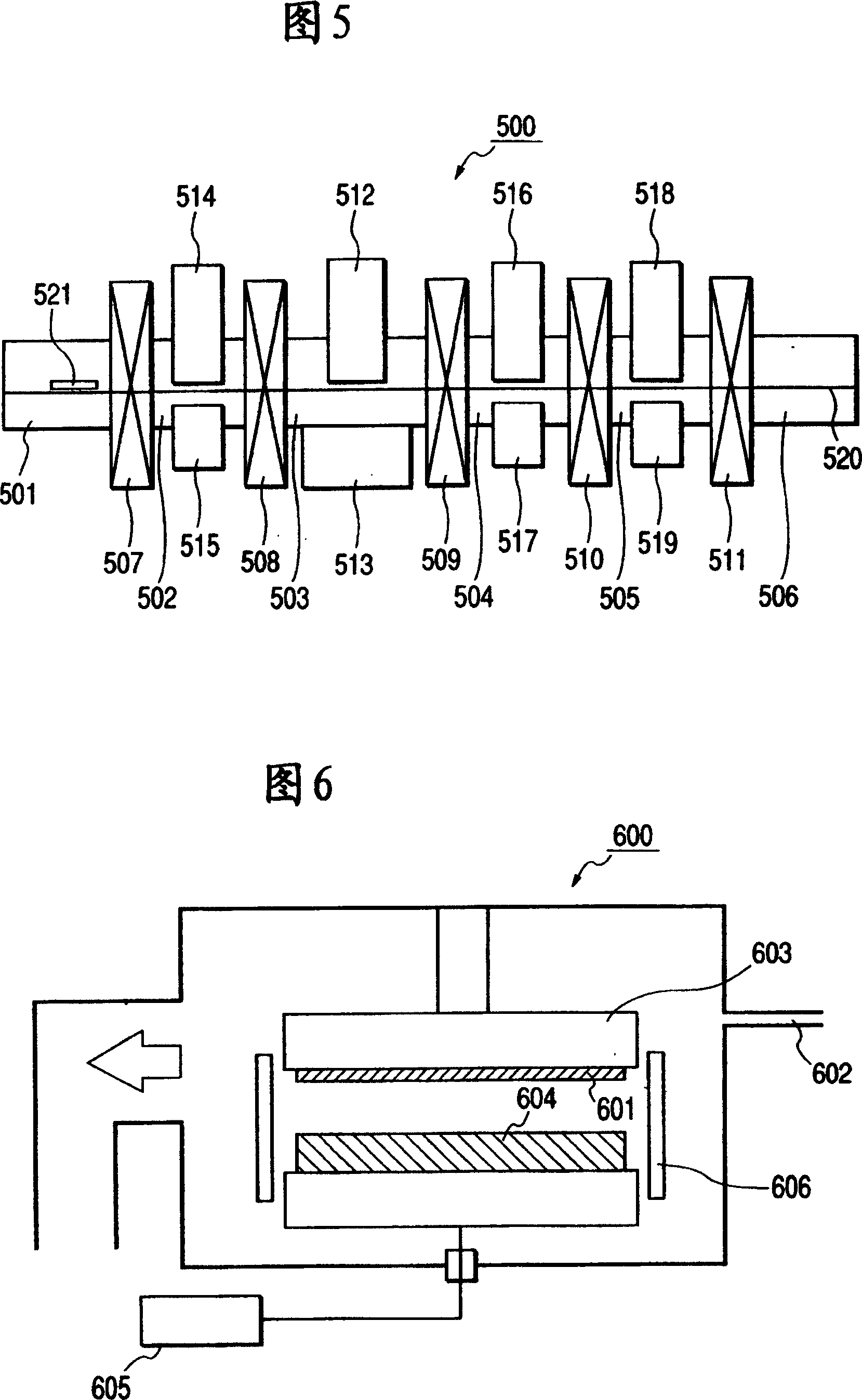
[0100] For the substrate 301, a flat stainless steel (SUS 430) generally called BA standard with a shape of 45 mm x 45 mm in length and width and a thickness of 0.15 mm was used, and it was installed in a commercially available DC magnetron sputtering device (not shown), Exhaust to bring the pressure to 10 -3 Pa or lower.

[0101] After that, with a flow rate of 30cm 3 / min (normal) supply argon to keep the pressure at 2×10 -1 Pa. Without heating the substrate, a 120W DC power was applied to a φ6-inch aluminum target to form a 70nm alumin...

Embodiment 2

[0147] In the same manner as in Example 1, a pin-type photoelectric element whose i layer is intrinsic microcrystalline Si is used as the second photoelectric element 302, and a pin-type photoelectric element whose i layer is intrinsic amorphous Si:H is used as the first photoelectric element 305, and a multilayer photoelectric element using zinc oxide as an intermediate layer (see FIG. 3 ).

[0148] The sample of the zinc oxide layer is produced separately from the photoelectric element, and the target material containing Al is adjusted as it is with oxygen and vaporized H 2 A zinc oxide layer showing the conductivity shown in Table 9 was formed on the quartz plate while increasing the amount of O introduced. From this result, it can be seen that there are conditions for forming a zinc oxide layer having a so-called graded resistivity in which the resistivity changes slowly in the layer thickness direction of the zinc oxide layer.

[0149] In addition, similarly to Example 1...

Embodiment 3

[0158] In Example 3, a pin-type optoelectronic element whose i layer is intrinsic amorphous Si:H is used as the first optoelectronic element, and a pin-type optoelectronic element whose i layer is intrinsic microcrystalline Si is used as the second optoelectronic element, and A third multi-layer photoelectric element of the present invention as shown in FIG. 8, in which indium tin oxide and zinc oxide are laminated as an intermediate layer.

[0159] For the substrate 801 in FIG. 8 , a flat stainless steel (SUS430) generally called BA standard with a shape of 45 mm x 45 mm in length and width and a thickness of 0.15 mm was used, and it was installed in a commercially available DC magnetron sputtering device (not shown). , ventilate to a pressure of 10 -3 Pa or lower.

[0160] After that, with a flow rate of 30cm 3 / min (normal) supply argon to keep the pressure at 2×10 -1 Pa. Without heating the substrate, a 120W DC power was applied to a φ6-inch aluminum target to form a 7...


PUM

PropertyMeasurementUnit
electrical resistivityaaaaaaaaaa
thicknessaaaaaaaaaa

Abstract

A stacked photovoltaic element comprising a plurality of unit photovoltaic elements each composed of a pn- or pin-junction, connected to each other in series, wherein a zinc oxide layer is provided at least in one position between the unit photovoltaic elements, and the zinc oxide layer has resistivity varying in the thickness direction.

Description

technical field [0001] The present invention relates to a laminated photoelectric element having at least two or more types of power generating functional units and a manufacturing method thereof. Background technique [0002] A photoelectric element is a device that converts incident light energy into electrical energy. A solar cell is a device that converts sunlight, which is white light, into electrical energy. It is a photoelectric element characterized by efficiently converting light in a wide wavelength range. Therefore, light must be absorbed without waste over a broad wavelength region in order to achieve high conversion efficiency. [0003] As one of the solutions to this problem, there is known a multilayer photovoltaic element in which photovoltaic elements including photoactive layers with different band gaps are laminated. This multilayer photovoltaic element is a photovoltaic element using a photoactive layer with a relatively large band gap on the light incid...

Claims


Application Information

Patent Timeline
Patent Type & Authority Patents(China)
IPC IPC(8): H01L31/04H01L31/06H01L31/18H01L31/00H01L31/052H01L31/0687H01L31/076H01L31/20
CPCH01L31/0687H01L31/076Y02E10/548Y02E10/544Y02E10/50H01L31/1824H01L31/202H01L31/046H01L31/0549Y02E10/52Y02E10/545Y02E10/547Y02P70/50
Inventor 松田高一东川诚中村哲郎
Owner CANON KK
Why Eureka
Try Eureka