

Computer system and speed-controlling method of cooling fan
A computer system, speed control technology, applied in the direction of DC motor speed/torque control, calculation, control system, etc., can solve the problems of peripheral circuit failure, circuit change, etc.
Inactive Publication Date: 2002-01-23
TOSHIBA CLIENT SOLUTIONS CO LTD
View PDF0 Cites 47 Cited by
- Summary
- Abstract
- Description
- Claims
- Application Information
AI Technical Summary
Problems solved by technology
Therefore, in the conventional control based only on the temperature of the CPU, the circuit may become hotter than expected, causing failure in the peripheral circuit.
Method used
View moreImage
Smart ImageViewing Examples

Examples
Embodiment Construction
Login to View More PUM
 Abstract
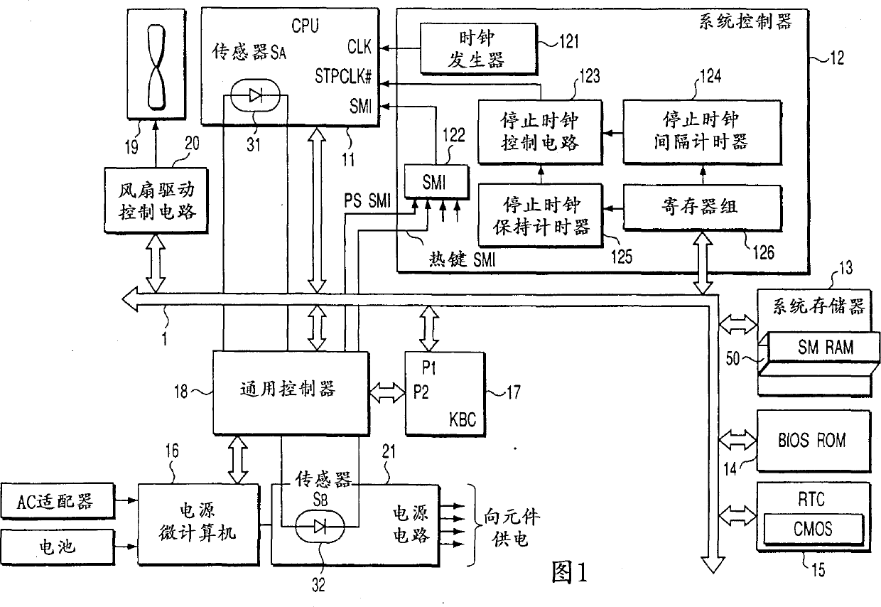
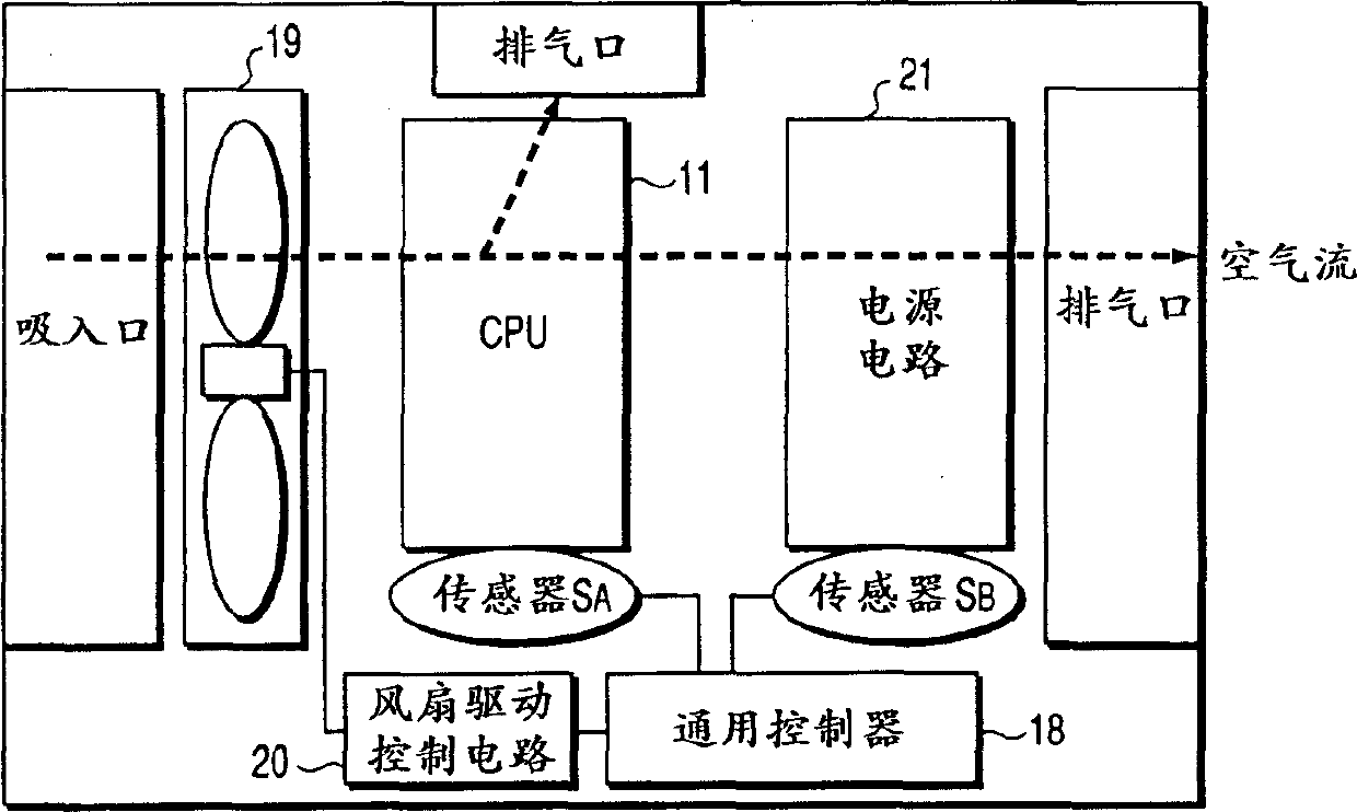
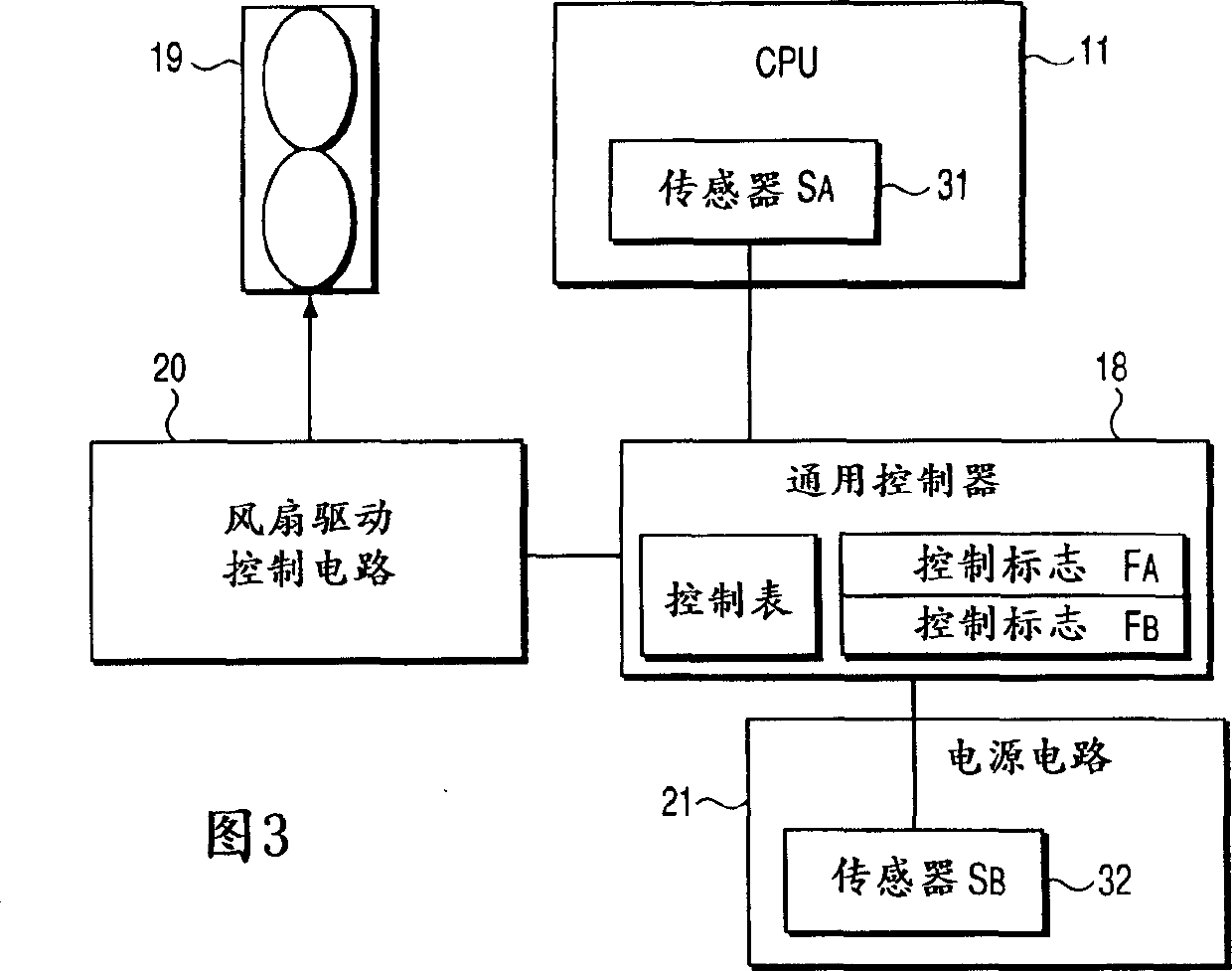
A cooling fan 19 cools both CPU 11 and an electric supply circuit 21. A temperature sensor 32 are installed on CPU 11 and the electric circuit 21 respectively. A general purpose controller 18 is equipped with a control flag that performs on-off action in accordance with the detected value of the temperature sensor. The general purpose controller 18 is provided with a control table in order to determine the rotation number of the cooling fan in accordance with the combination of each status of these flags, and determines the rotation number referring to these control flags and the control table, and indicates a fan driving control circuit 20 to control the driving of the cooling fan 19 based on the determined rotation number. Thereout, it can cool a heating element efficiently and safely suppressing the generation of noise.
Description
technical field The invention relates to a computer system and a cooling fan speed control method, in particular to a cooling fan speed control method suitable for a computer system equipped with a CPU with a power-saving mode. Background technique In recent laptop or notebook personal computer systems, not only the CPU temperature needs to be reduced, but also the surface temperature of the chassis is highly required. In particular, it is necessary to suppress the rise in the surface temperature of the case caused by the heat generated by the power supply circuit. In addition, since rotating the cooling fan is accompanied by shortening of the battery-operable time or generating noise, it is required not to rotate the fan as much as possible or to increase the number of rotations of the fan (per unit time) as much as possible. For this reason, it is desired to efficiently cool the CPU and the power supply circuit by the cooling fan. However, because the CPU generates the...
Claims
Login to View More Application Information
Patent Timeline
 Patent Type & AuthorityApplications(China)
IPC IPC(8): G06F1/26G06F1/20H01L23/34H05K7/20
CPCG06F1/206H01L23/34H01L2924/0002H01L2924/00
Inventor松下聪
OwnerTOSHIBA CLIENT SOLUTIONS CO LTD