Internal cutter of electric rotary shaver and electric rotary shaver

An electric rotary, shaver technology, used in metal processing and other directions, can solve problems such as difficult hair removal

Inactive Publication Date: 2002-02-06
IZUMI PROD CO
View PDF0 Cites 7 Cited by
  • Summary
  • Abstract
  • Description
  • Claims
  • Application Information

AI Technical Summary

Problems solved by technology

Furthermore, unlike the upper surface of the knife holder 26 which is intended to collect hairs, the hair-collected inside

Method used


Image

  • Internal cutter of electric rotary shaver and electric rotary shaver
  • Internal cutter of electric rotary shaver and electric rotary shaver
  • Internal cutter of electric rotary shaver and electric rotary shaver

Examples


Embodiment Construction

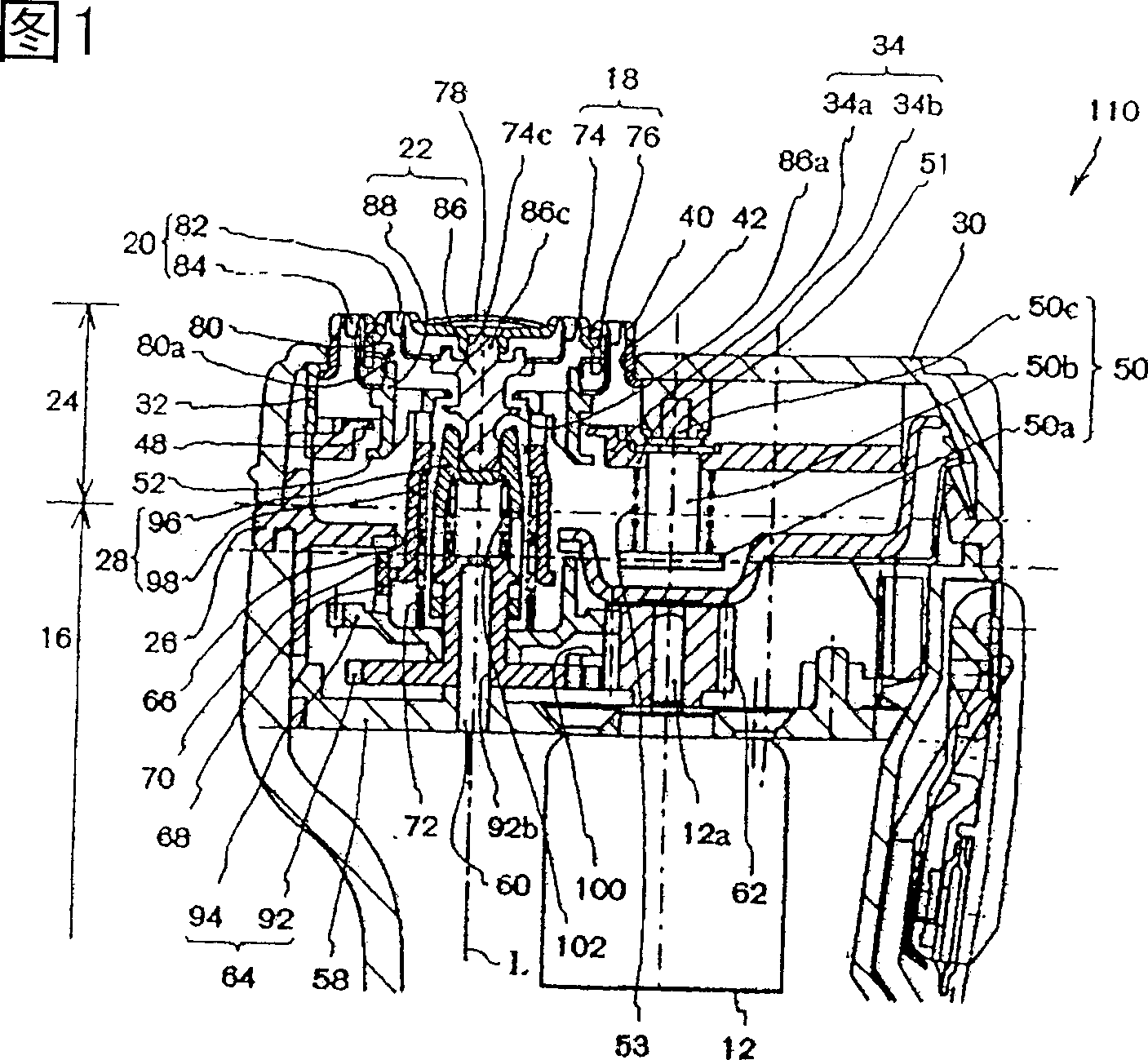
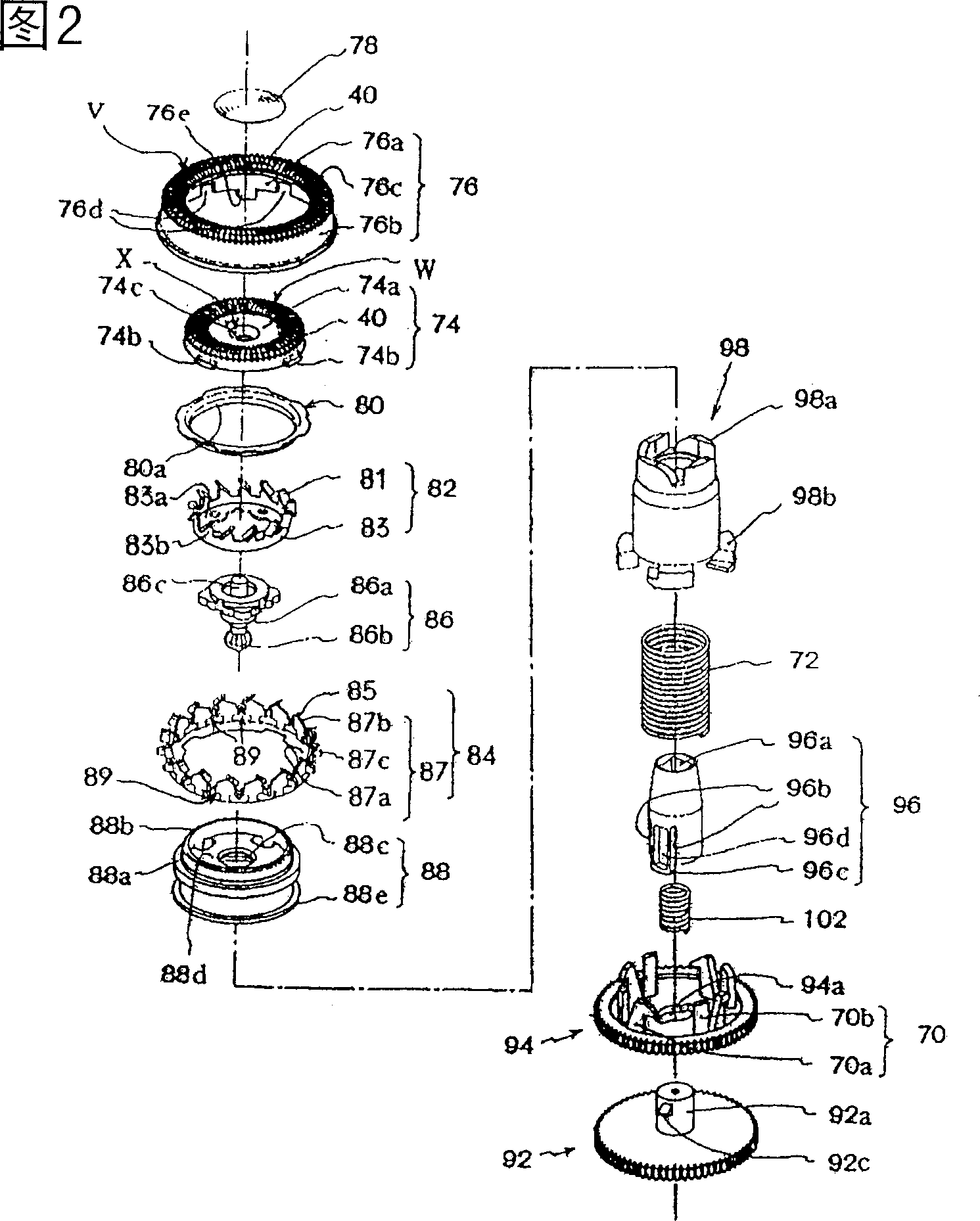
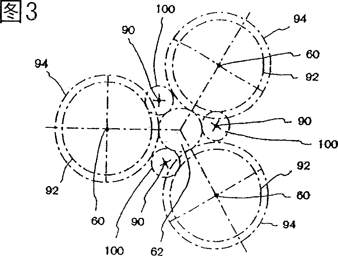
[0083] Preferred embodiments of the present invention will be described in detail below with reference to the accompanying drawings. The same structures as in the conventional electric rotary shaver 10 are denoted by the same reference numerals, and a detailed description of such structures is omitted.

[0084] First of all, the overall appearance of the electric rotary shaver in this embodiment is basically the same as Figure 7 Same as conventional electric rotary shavers shown. However, the internal structure of the razor of the present invention is different from conventional razors. Therefore, the electric rotary shaver of the present invention will be described with reference to conventional shaver Figure 7 and Figure 1 for description.

[0085] The electric shaver 10 is composed of a main body casing 16 and a cutter head section 24, the cutter head section is detachably mounted on the upper part of the main body casing 16 and accommodates the outer cutter 18, the inne...


PUM


Abstract

An inner cutter for an electric rotary shaver, the inner cutter comprising a cutter supporting member and an inner cutter body. The cutter supporting member has a ring-form body formed in a shape of a flat plate and is provided with a plurality of upright supporting portions that rise from an outer-circumferential edge of the ring-form body and are lined up side by side. The inner cutter body is formed on the tip end of each one of the upright supporting portions. Gaps are formed between adjacent upright supporting portions, and ribs are provided between the adjacent upright supporting portions, thus allowing cut hair to be discharged out of the inner cutter through openings defined by the adjacent upright supporting portions and ribs.

Description

field of invention [0001] The invention relates to an inner cutter of an electric rotary shaver and a rotary electric shaver. Background technique [0002] Refer below Figure 7 and 8 A conventional electric rotary shaver is described. [0003] Firstly, the overall structure will be described. The electric shaver 10 mainly includes a main body shell 16 and a cutter head section 24 . The main body casing 16 is made of synthetic resin, and is held in the user's hand while shaving hair, beard, mustache, etc. (referred to as hair). The main body housing 16 accommodates a motor 12, a power switch 14, a power supply part (not shown) for supplying electric power to the motor 12, and other components. The cutter head section 24 is detachably mounted on the upper end of the main body housing 16 and has an outer knife 18 , an inner knife 20 , an inner knife seat 22 for the inner knife 20 , etc., which are built in the cutter head section 24 . [0004] Figure 7 and 8 An electric ...

Claims


Application Information

Patent Timeline
IPC IPC(8): B26B19/14
CPCB26B19/141B26B19/145
Inventor 中野毅
Owner IZUMI PROD CO
Why Eureka
Try Eureka