Method and apparatus for checking cutting tools
A cutting tool and cutting technology, applied in the direction of manufacturing tools, metal processing equipment, measuring/indicating equipment, etc., can solve problems such as ineffective use of tools, uneven tool replacement periods, and work efficiency deterioration.
- Summary
- Abstract
- Description
- Claims
- Application Information
AI Technical Summary
Problems solved by technology
Method used
Image
Examples
no. 1 Embodiment
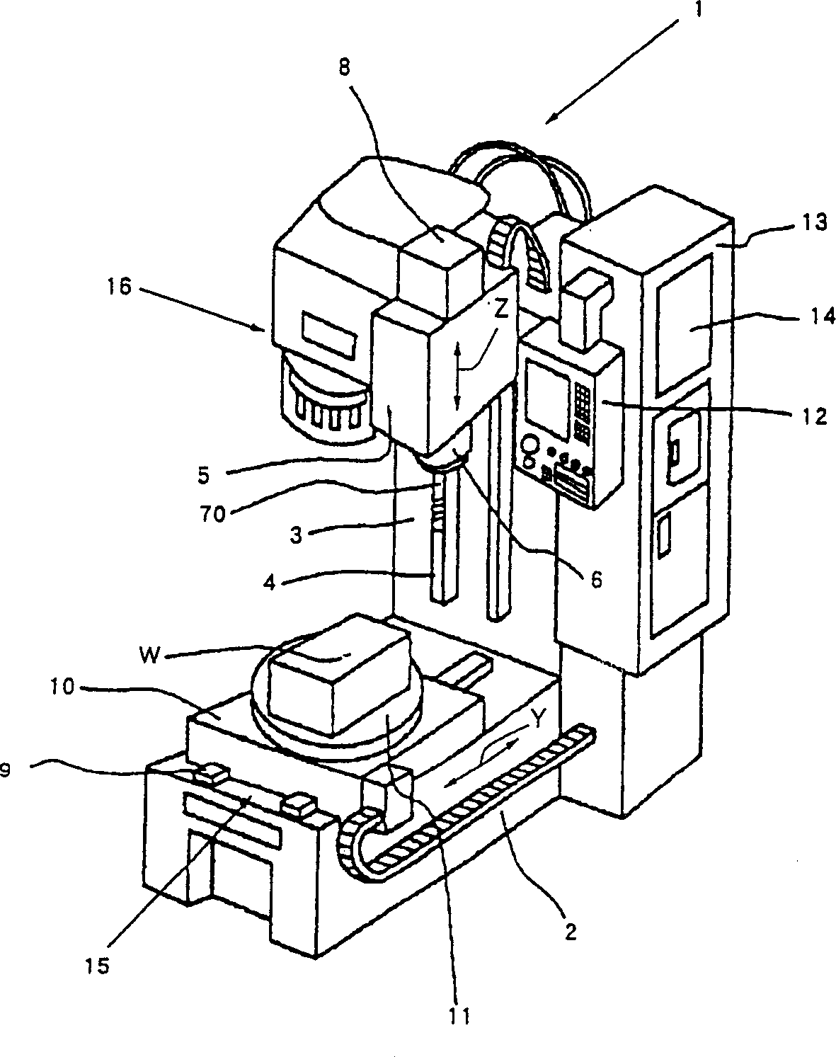
[0046] Figure 4 Among them, the vibration detection sensor 17 detects the vibration of the cutting tool 70, that is, detects the vibration of the cutting tool 70 when cutting the workpiece W, the preamplifier 18 amplifies the detection signal of the vibration detection sensor 17, and the filter 19 transmits the signal from the preamplifier Noise components are removed from the amplified signal at 18, and only the signal representing the vibration of the cutting tool 70 is extracted, that is, only the time-varying signal of the vibration is extracted. The A / D converter 20 converts the output signal of the filter 19 from an analog signal to a digital signal, and the signal processing control unit 21 applies predetermined processing described later to the digital signal passed through the A / D converter 20 .
[0047] The aforementioned vibration detector 17 is, for example, an acoustic emission sensor AE. In order to detect the vibration of the cutting tool, it should be installe...
no. 2 Embodiment
[0061] Hereinafter, the second embodiment will be described.
[0062] This example focuses on Figure 11 As shown, the integral value of the vibration waveform that occurs within a certain period of time normally does not change with time, but as Figure 12 As shown, when the wear of the cutting tool increases, the integrated value of the vibration waveform generated within a certain period of time changes with time, and detecting this change can detect the abnormal state of the cutting tool.
[0063] In the above-mentioned first embodiment, the signal processing control unit 21 is provided with a peak detection unit 22 that detects the frequency of vibration peak occurrences. The signal processing control unit 21 of this embodiment is as follows Figure 10 As shown, there is a waveform integration unit 27 that integrates the vibration waveform detected by the vibration detection sensor 17 every set time.
[0064] In addition, the signal processing control unit 21 is provide...
no. 3 Embodiment
[0071] Next, a third embodiment will be described.
[0072] It is noted in this embodiment that if frequency analysis is performed on the vibration waveform, such as Figure 16 As shown, under normal conditions, the fundamental frequency component determined by the rotational speed of the cutting tool 70 and the number of cutting edges 27 is overwhelmingly larger than other frequency components, while under abnormal conditions, it is as follows Figure 17 As shown, the fundamental frequency component is almost indistinguishable from other frequency components, and detection of this change also detects abnormality of the cutting tool.
[0073] As shown in FIG. 14 , the signal processing control unit 21 of the present embodiment has: the vibration waveform detected by the vibration detection sensor 17 is subjected to frequency analysis, for example, a frequency analysis unit 30 that applies Fourier analysis, and the frequency analysis unit 30 is configured by the frequency analy...
PUM
 Abstract
Description
Claims
Application Information
 - R&D
- Intellectual Property
- Life Sciences
- Materials
- Tech Scout
- Unparalleled Data Quality
- Higher Quality Content
- 60% Fewer Hallucinations
Browse by: Latest US Patents, China's latest patents, Technical Efficacy Thesaurus, Application Domain, Technology Topic, Popular Technical Reports.
© 2025 PatSnap. All rights reserved.Legal|Privacy policy|Modern Slavery Act Transparency Statement|Sitemap|About US| Contact US: help@patsnap.com


