
Eureka
For R&D, Eureka makes reading and utilizing patents & technical documents easy.
Eureka AIR
Designed for self-driven R&D workflows. Generate viable solutions, solve complex R&D challenges, empower your innovation with AI.

Eureka Materials
Designed for material experts only. Revolutionize your material R&D, from search, analyze, to developing new materials.

TechResearch
Generate reliable direction feasibility study reports for your R&D in just a few steps.

TechSeek
Discover and master advanced knowledge NOW. Basics, ideas, possibilities, all at once.

TechMind
As an expert in R&D Theories, TechMind can generates customized viable solutions instantly.

TechRisk
Analyze your overall solution with one click, know your potential R&D risks in advance.

TechMonitor
Get weekly tech updates, stay abreast of the latest tech innovations and key insights.
Protection relay and protected control set with front wiring
A technology for protecting relays and relays, which is applied in the direction of emergency protection devices, relays, thermal relays, etc.
- Summary
- Abstract
- Description
- Claims
- Application Information
AI Technical Summary
Problems solved by technology
Method used
Image


Examples
Embodiment Construction
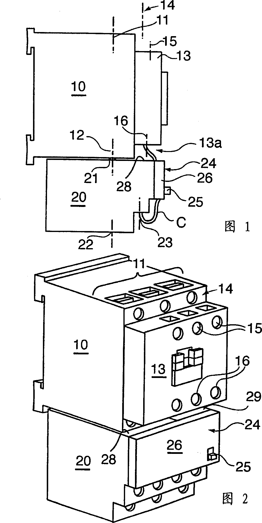
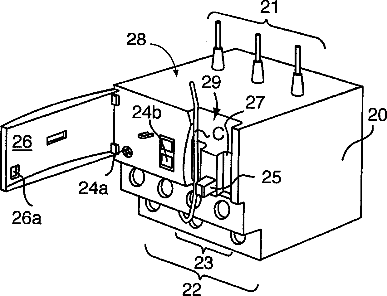
[0015] The illustrated control and protection device comprises a circuit closer with a case 10 and a thermal protection relay with a case 20 fitted to the circuit closer. The circuit closer box 10 has an input power terminal 11 and an output power terminal 12, and a control-manipulation terminal block 13 on the front side, in other words, on the side accessible to the user. The term "control" mentioned in the following description is distinguished from the manipulation (or signal transmission) and control (or switching) functions of changing the state of the circuit closer by supplying power to the circuit closer coil. The control terminal block 13 is provided with an input-side control terminal 15 and an output-side control terminal 16, which can be respectively connected to a high voltage and a low voltage, and the control terminal block 13 protrudes forward beyond the front surface 14 of the box body 10, where The box body has a plurality of openings, and the tools can acce...
PUM
 Abstract
Description
Claims
Application Information
 - R&D Engineer
- R&D Manager
- IP Professional
- Industry Leading Data Capabilities
- Powerful AI technology
- Patent DNA Extraction
Browse by: Latest US Patents, China's latest patents, Technical Efficacy Thesaurus, Application Domain, Technology Topic, Popular Technical Reports.
© 2024 PatSnap. All rights reserved.Legal|Privacy policy|Modern Slavery Act Transparency Statement|Sitemap|About US| Contact US: help@patsnap.com