Refrigeration cycle device for vehicle

a technology for refrigeration cycle devices and vehicles, which is applied in refrigeration components, transportation and packaging, light and heating equipment, etc., to achieve the effect of suppressing the increase of refrigerant pressur

Inactive Publication Date: 2006-10-26
DENSO CORP
View PDF16 Cites 43 Cited by
  • Summary
  • Abstract
  • Description
  • Claims
  • Application Information

AI Technical Summary

Benefits of technology

[0005] The present invention has been implemented in view of the foregoing problem, and has an object to provide a refrigeration cycle device for a vehicle that can suppress increase of refrigerant pressure.

Problems solved by technology

Particularly in the refrigeration cycle device for a vehicle, as compared with the increase of the refrigerant pressure due to increase of the ambient temperature such as the outside air temperature or the like, the increase of the refrigerant pressure is more greatly affected by heat occurring from an engine, etc. during travel of the vehicle, so that the increase of the refrigerant pressure when the compressor is under the stopped state causes a more critical problem.

Method used


Image

  • Refrigeration cycle device for vehicle
  • Refrigeration cycle device for vehicle
  • Refrigeration cycle device for vehicle

Examples


first embodiment

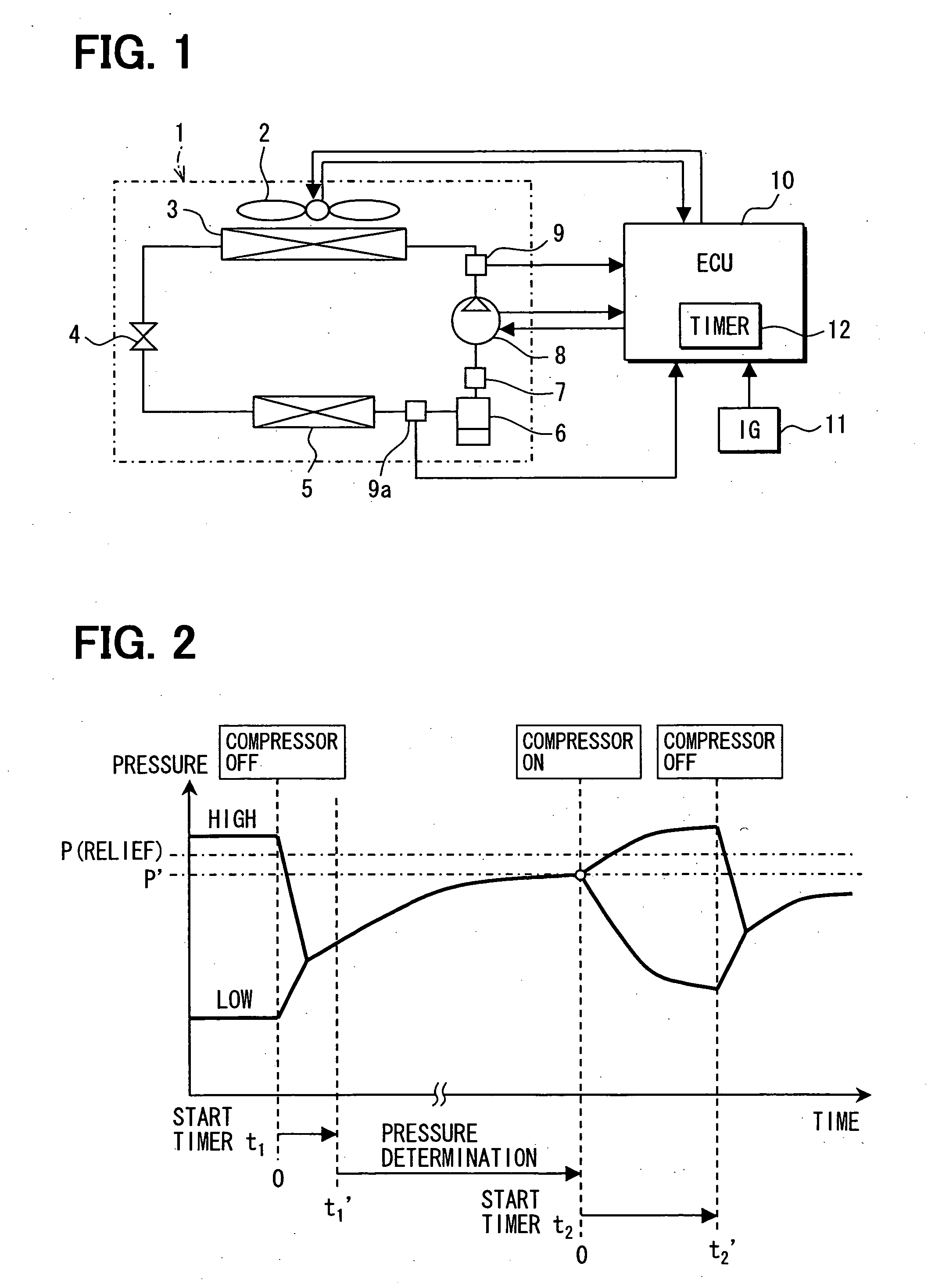
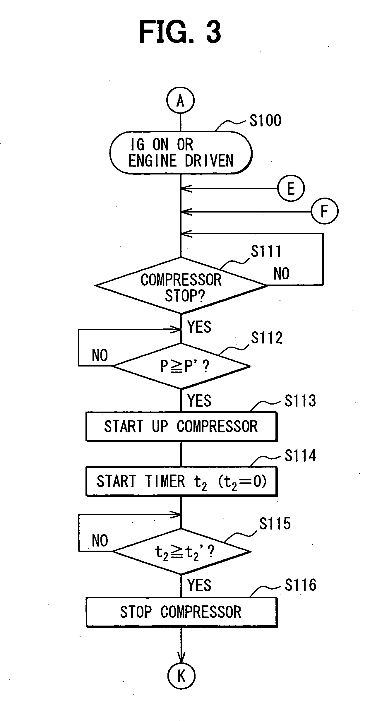
[0053] A refrigeration cycle device for a vehicle according to a first embodiment carries out inherent control to reduce refrigerant pressure in a refrigerant cycle using refrigerant containing carbon dioxide (CO2) as a main component so that parts in the refrigerant cycle can be prevented from being damaged due to increase of the refrigerant pressure. Particularly, the refrigeration cycle device for a vehicle is peculiar and different from a stationary refrigeration cycle device in that the increase of the refrigerant pressure is greatly affected by heat occurring when a vehicle engine is driven unlike.

[0054] In order to solve the problem under such a peculiar condition, the vehicle refrigeration cycle device of this embodiment is controlled in consideration of the effect of heat occurring when the vehicle travels. Particularly, one factor causing the increase of the refrigerant pressure in the refrigerant cycle which is applied to the vehicle environment is as follows. That is, w...

second embodiment

[0124] This embodiment is different from the first embodiment in that temperature data are used for the condition detection based on the condition detecting unit. In the supercritical refrigerant cycle, when refrigerant is sealed at some cycle sealing density, if the cycle average temperature at that time is increased, the sealed refrigerant falls into the supercritical state, and the pressure is determined by the temperature at that time. Therefore, according to this embodiment, the refrigerant detection is detected by detecting the refrigerant temperature.

[0125] Next, the second embodiment will be described with reference to FIGS. 8 to 17. The same constituent elements as the first embodiment are represented by the same reference numerals.

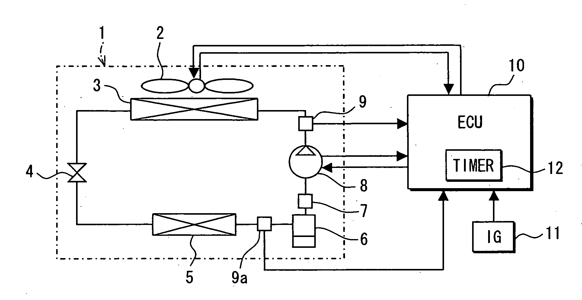
[0126]FIG. 8 is a diagram showing the construction of a refrigeration cycle device for a vehicle according to the second embodiment. As shown in FIG. 8, the refrigerant cycle 20 includes a compressor 8, a discharge temperature sensor 13 serving...

third embodiment

[0182] In the third embodiment, under the state that the ignition (IG) switch is set to OFF, the compressor or the cooling fan is started up at the condition detection time, and then the stop control is carried out as in the case of FIGS. 3, 5 and 12. The different point of the third embodiment from the first and second embodiments resides in that an electrically-driven compressor and an electrically-driven cooling fan is controlled in place of the compressor 8 and the cooling fan 2 to keep the refrigerant pressure proper. The third embodiment will be described hereunder with reference to FIGS. 18 to 21.

[0183]FIG. 18 is a control flowchart showing the processing of reducing the refrigerant pressure by controlling the electrically-driven compressor on the basis of the detection value of the refrigerant pressure when the ignition (IG) switch is set to OFF.

[0184] In this control flow shown in FIG. 18, first, when the ignition (IG) switch is set to OFF (step S170), it is determined wh...


PUM


Abstract

A refrigeration cycle device for a vehicle includes a condition detecting unit for detecting a condition that an inner pressure of the refrigerant cycle exceeds a control set pressure, and a pressure reducing unit for reducing a pressure of the refrigerant at a low pressure side of a refrigerant cycle when the condition is detected. For example, when the condition detecting unit detects the condition, the pressure reducing unit starts up a compressor of the refrigerant cycle so as to reduce the pressure at the low pressure side in the refrigerant cycle.

Description

CROSS REFERENCE TO RELATED APPLICATION [0001] This application is based on Japanese Patent Applications No. 2005-127000 filed on Apr. 25, 2005, and No. 2006-55384 filed on Mar. 1, 2006, the contents of which are incorporated herein by reference in its entirety. FIELD OF THE INVENTION [0002] The present invention relates to a vehicle refrigeration cycle device using refrigerant containing carbon dioxide (CO2) as a main component, for example. BACKGROUND OF THE INVENTION [0003] As one of this type of refrigeration cycle devices is known a refrigeration cycle device equipped with a compressor in which the discharge capacity thereof is variable in accordance with a control amount input from the external and the pressure of refrigerant can be increased up to a supercritical area, a heat radiator for cooling the refrigerant compressed by the compressor, an expansion device for reducing the pressure of the refrigerant cooled by the heat radiator, and an evaporator for evaporating the refri...

Claims


Application Information

Patent Timeline
Patent Type & Authority Applications(United States)
IPC IPC(8): F25B39/04F25B49/00F25B1/00
CPCB60H1/3219F25B2700/21173F25B9/008F25B49/005F25B2309/061F25B2600/0251F25B2600/0253F25B2600/111F25B2700/1931F25B2700/1933F25B2700/197F25B2700/2104F25B2700/2106F25B2700/2117B60H2001/325
Inventor MIZUNO, SYUICHINISHIDA, SHINITOH, SATOSHIKAKEHASHI, NOBUHARU
Owner DENSO CORP
Why Eureka
Try Eureka