Low-noise hydraulic planger pump with energy accumulator

A technology of hydraulic plunger pumps and accumulators, which is applied in the direction of pumps, multi-cylinder pumps, machines/engines, etc., and can solve problems such as poor adaptability and poor adaptability

Inactive Publication Date: 2002-07-03
ZHEJIANG UNIV
View PDF0 Cites 6 Cited by
  • Summary
  • Abstract
  • Description
  • Claims
  • Application Information

AI Technical Summary

Problems solved by technology

2. It has a good effect on pumps with constant working conditions such as constant pressure and fixed quantity, but poor adaptability to variable pressure and variable pumps
2. When the working condition deviates too much from the rated working condition, the adaptability is not good

Method used


Image

  • Low-noise hydraulic planger pump with energy accumulator
  • Low-noise hydraulic planger pump with energy accumulator
  • Low-noise hydraulic planger pump with energy accumulator

Examples


Embodiment Construction

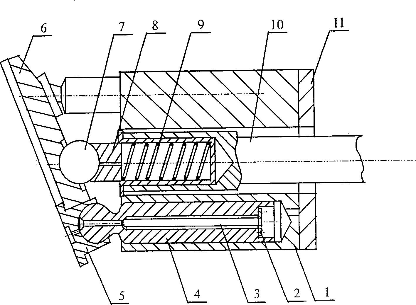
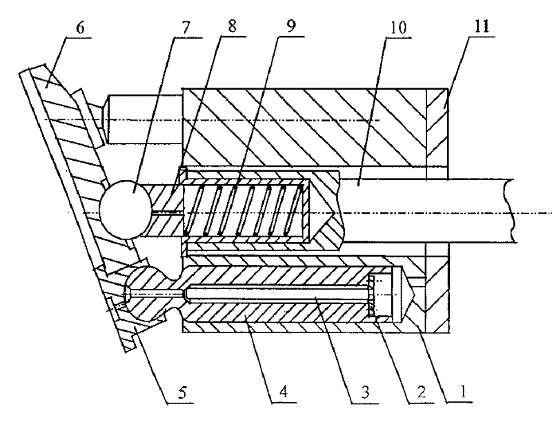
[0012] Such as figure 1 Shown is a schematic diagram of the structure of a low-noise hydraulic plunger pump with an accumulator. Including cylinder 1, flange 2, accumulator 3, plunger 4, sliding shoe 5, pressure plate 6, steel ball 7, inner sleeve 8, spring 9, main shaft 10, valve plate 11; accumulator 3 is installed on In the central small through hole of the plunger 4, a flange 2 with several small through holes in the axial direction is installed on the inner end surface of the large central hole of the plunger near the end of the valve plate.

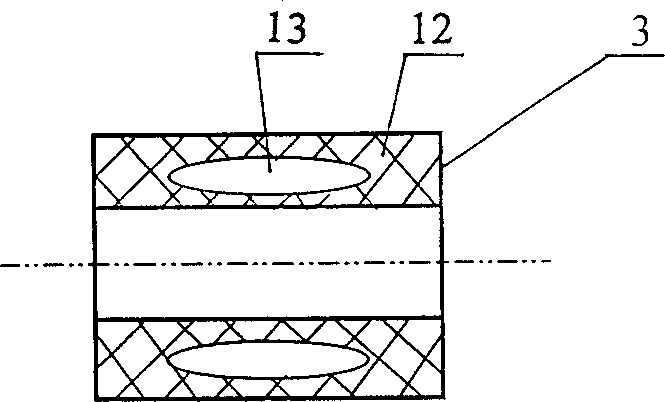
[0013] Such as figure 2 A schematic diagram of the structure of the accumulator is shown. The accumulator 3 is made of non-metallic material, and the non-metallic material 12 contains a little high-pressure gas 13 to play the role of energy storage and energy release.

[0014] When the plunger cavity transitions from the oil suction area to the oil discharge area, the plunger cavity filled with low-pressure oil suddenly connects...


PUM


Abstract

A low-noise hydraulic plunger pump with energy accumulator installed in the central through hole of plugner is composed of cylinder, flange, energy accumulator, plunger, slide block, pressing disk, steel ball, inner sleeve, spring, mainshaft and flow distributor. Its advantages include accumulating and releasing energy to reduce pressure ripple, and low noise.

Description

technical field [0001] The invention relates to a low-noise hydraulic plunger pump with an accumulator. technical background [0002] The fluid noise of the plunger pump is mainly generated by the flow distribution process. During the flow distribution process, when the plunger cavity transitions from the oil suction area to the oil discharge area, the plunger cavity filled with low-pressure oil suddenly connects with the high-pressure oil in the oil discharge area, causing high-pressure oil to enter the plunger cavity from the oil discharge area, forming Flow backflow impact. With the increase of the pressure of the plunger and the backflow flow, the pressure in the plunger chamber rises to be equal to the pressure of the oil discharge area. As the plunger continues to be pressed in, the plunger chamber enters the oil discharge working condition. However, due to the inertia and damping effect of the oil, the discharge of the oil is restricted, and the pres...

Claims


Application Information

Patent Timeline
Patent Type & Authority Applications(China)
IPC IPC(8): F04B1/12
Inventor 傅新杨俭杨华勇
Owner ZHEJIANG UNIV
Why Eureka
Try Eureka