Laser-ultrasonic measurement of wall thickness

A technology of ultrasonic and laser devices, applied in measuring devices, measuring heat, using ultrasonic/sonic/infrasonic waves, etc., can solve problems such as large complexity and high cost

Inactive Publication Date: 2002-07-03
NAT RES COUNCIL OF CANADA
View PDF4 Cites 12 Cited by
  • Summary
  • Abstract
  • Description
  • Claims
  • Application Information

AI Technical Summary

Problems solved by technology

Thus, 10 systems are required, leading to enormous complexity and prohibitive cost

Method used


Image

  • Laser-ultrasonic measurement of wall thickness
  • Laser-ultrasonic measurement of wall thickness
  • Laser-ultrasonic measurement of wall thickness

Examples


Embodiment Construction

[0030] Detailed Description of Preferred Embodiments

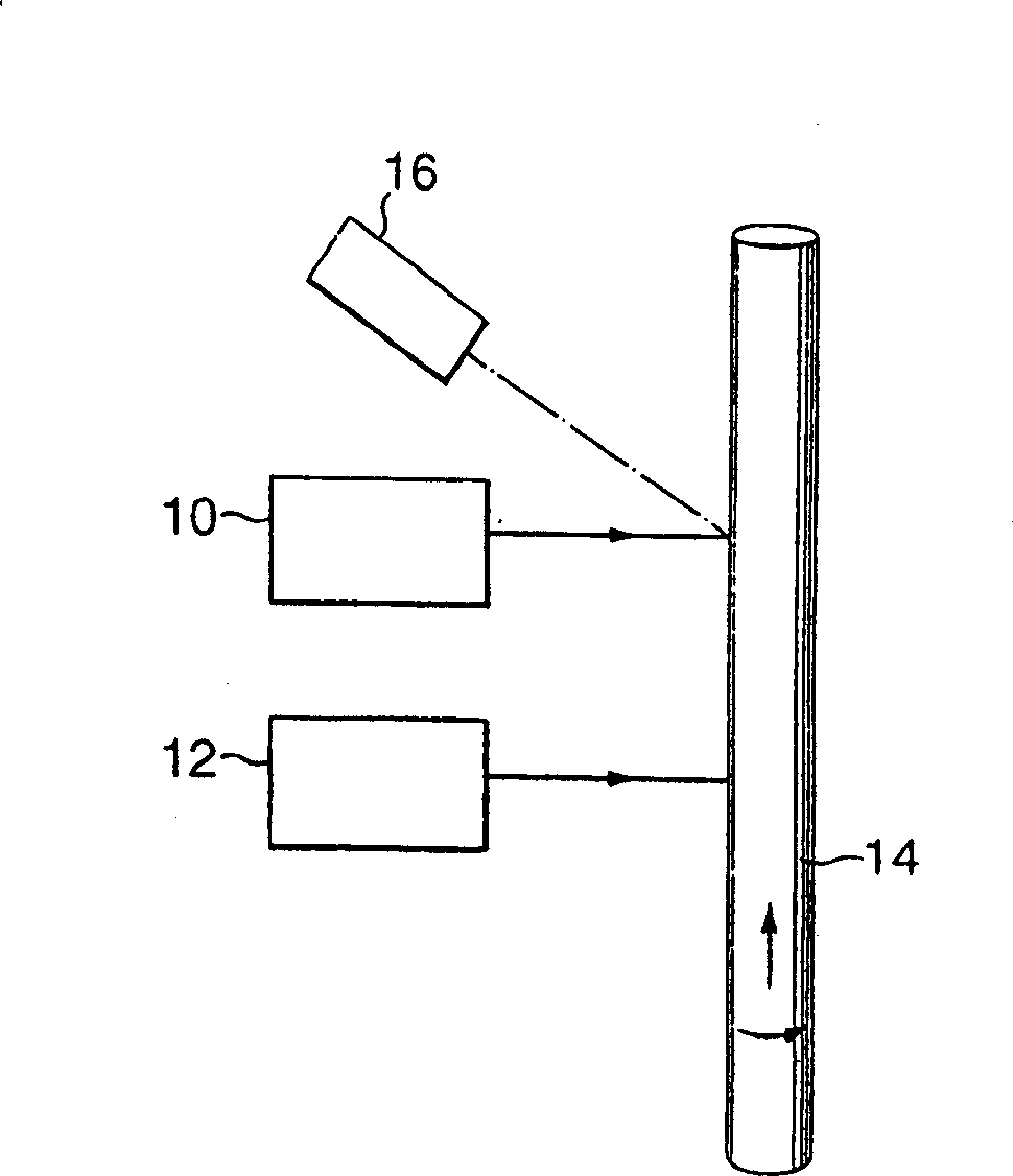
[0031] The invention is firstly based on measuring the wall thickness at specific locations using a single laser-ultrasonic system coupled to an optical system for measuring the displacement of the pipe. Since the tube rotates and translates (similar to a screw motion), the optical system must measure displacement in both directions. A general embodiment of the invention is shown in figure 1 Among them, it includes a laser-ultrasonic subsystem 10 for measuring wall thickness at a specific location and a displacement measurement subsystem for tracking the movement of the pipe from one thickness (pipe is generally indicated by 14) measurement location to the next. Such as figure 1 As shown, since the tube is a rigid body, the measurement position of the displacement can be selected at a different place from the thickness measurement position. figure 1 Also shown is an optical pyrometer used to measure the temperature of t...


PUM


Abstract

An apparatus and method for mapping out wall thickness of a tube or other object having motion in two directions. The device includes a first laser for generating ultrasound propagating inside tube wall over a particular generation spot on a surface of the tube, a second laser coupled to an interferometer for detecting produced ultrasonic echoes over a detection spot on the surface. A processor is provided for operating on recorded ultrasonic echoes and using a given value of ultrasonic velocity and the distance between the generation spot and the detection spots for determining wall thickness at a mid-point between the generation and detection spot. An optical displacement measuring device determines a displacement in two dimensions between the generation spot and arbitrary starting spot and a display for displaying wall thickness values over the surface of the tube.

Description

field of invention [0001] The present invention relates to a method and an apparatus for measuring and mapping the wall thickness of pipes in rotational and translational motion and possibly at high temperatures, directly on the production line. More specifically, the method and apparatus are based on the use of lasers to generate and detect ultrasound. Background of the invention [0002] Tubes and pipes are widely used products and can be manufactured by various processes. They can be made seamed by bending a flat plate and welding, or they can be made seamless. The use of rotary punching technology to manufacture steel pipes for special applications, such as steel pipes for oil drilling, is one of the seamless production processes. In this rotary punching process, a mandrel is forcibly punched into a hot circular blank. In the process, the circular blank is driven to rotate by two rollers. This method can also be used to make tubes (mechanical tubes) which are later cu...

Claims


Application Information

Patent Timeline
Patent Type & Authority Applications(China)
IPC IPC(8): G01B17/02B21C51/00G01B11/06G01K11/24G01N29/00
CPCG01K11/24G01B11/0691
Inventor J·-P·蒙查林A·布罗因C·帕蒂奥莱奥
Owner NAT RES COUNCIL OF CANADA
Why Eureka
Try Eureka