
Connecting rod type rubber caterpillar

A rubber crawler and connecting rod technology, which is applied to tracked vehicles, motor vehicles, transportation and packaging, etc., can solve the problems of discontinuous runner tracks, poor cushioning, and walking vibration, and achieve improved walking stability without fatigue accumulation , the effect of preventing rubber cracking

Inactive Publication Date: 2002-07-17
FUKUYAMA GOMU KOGYO
View PDF3 Cites 2 Cited by
  • Summary
  • Abstract
  • Description
  • Claims
  • Application Information

AI Technical Summary

Problems solved by technology

In the steel track, the upper surface of the track connecting rod becomes a continuous runner track, so that the vibration is small when walking, and there is no stretching in the circumferential direction and the width direction, and there is no lateral deviation, so the track is less likely to fall off. In addition, it also has Due to the high mechanical connection strength between the crawler links, it has the advantages of good durability. However, on the other hand, it has the disadvantages of high noise, poor cushioning, easy fatigue of the operator, and easy damage to the road surface.
[0004] On the contrary, rubber track has the advantages of low noise, good cushioning, no damage to the road surface, light weight, and fast walking speed. However, its disadvantage is that it is not as durable as steel track due to its poor mechanical strength. Large external forces are prone to problems such as circumferential elongation and width direction torsion, resulting in track detachment, and walking vibration due to discontinuous runner tracks.

Method used


Image

  • Connecting rod type rubber caterpillar
  • Connecting rod type rubber caterpillar
  • Connecting rod type rubber caterpillar

Examples


Embodiment Construction

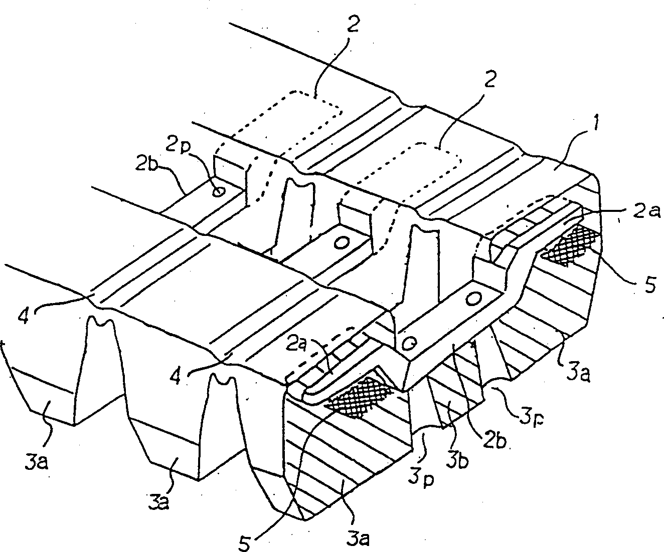
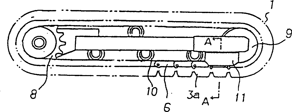
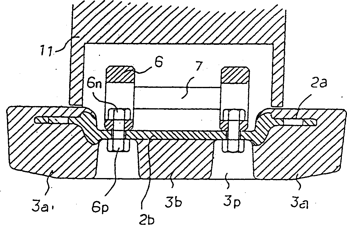
[0030] Hereinafter, embodiments of the present invention will be described with reference to the drawings. figure 1 For representing the perspective view of the connecting rod type rubber track of the present invention, figure 2 In order to show the overall side view of the connecting rod type rubber crawler walking device installed, image 3 for along figure 2 The cross-sectional view of the width direction cut by the line A-A in Figure 4 for figure 2 Enlarged view of part of .

[0031] In the figure, 1 is a rubber crawler main body, and a mandrel 2 having wings 2a, 2a extending left and right and a concave central part 2b is buried in the rubber crawler main body 1 at predetermined intervals, and a central part 2b is formed on the central part 2b. The bolt hole 2p of the crawler link 6 is installed with a bolt 6p and a nut 6n. 3a is the wing protrusion corresponding to the mandrel wing 2a protruding toward the side where the rubber track contacts the ground, 3b is ...


PUM


Abstract

The present invention relates to a connecting-rod type rubber crawler. A mandrel rod comprising a left wing, a right wing and a central part is, perpendicularly and at an approximately same space, embedded into the rubber crawler along the length direction with respect to the circumferencial direction of a rubber crawler main body. A protuberance is provided on the rubber crawler at the side on which the rubber crawler is brought into contact with the earth. The two sides of the upper central part of the mandrel rod is provided with crawler couplers and the front and the rear crawler couplers are connected with each other to a bend over state, thus to form a track by a pair of continuous crawler couplers. The invention is characterized in that a rubber crawler main body is made to continue to itself along its circumferential direction and on the outsides of stone guards projecting from the vehicle frame, curving portion is formed between adjacent mandrel rod wings toward their inner peripheries, and the width L1 of mandrel rod wings embedded into the connecting-rod type rubber crawler main body is shorter than the width L2 of the two outside parts of the installation position of the crawler couplers formed on the central part of the mandrel rod(L1 B62D 55 / 24 20 10 4 2001 / 7 / 30 1358647 2002 / 7 / 17 1125742 2003 / 10 / 29 2003 / 10 / 29 Fukuyama Gomu Kogyo K.K. Japan Kato Sukesaku Norito Tatsuya fang xiaogong 31100 Shanghai Patent Agency Building 34--35, No.2650 Zhongshan North Road, Shanghai 200063 Japan 1995 / 5 / 12 149371 / 1995 Japan 1995 / 11 / 7 324979 / 1995

Description

[0001] This case is a divisional application of the invention patent application with the application number 96102596.4, the application date is January 31, 1996, and the title is "connecting rod type rubber track and its mandrel". technical field [0002] The invention relates to a connecting rod type rubber crawler mounted on the bottom of walking construction machinery, civil engineering machinery and the like. Background technique [0003] In the past, steel crawlers were used without exception in walking construction machinery, however, rubber crawlers have been increasingly used in recent years. In the steel track, the upper surface of the track connecting rod becomes a continuous runner track, so that the vibration is small when walking, and there is no stretching in the circumferential direction and the width direction, and there is no lateral deviation, so the track is less likely to fall off. In addition, it also has Due to the high mechanical connection strength b...

Claims


Application Information

Patent Timeline
Patent Type & Authority Applications(China)
IPC IPC(8): B62D55/08B62D55/18B62D55/205B62D55/24B62D55/253
Inventor 加藤祐作乘藤达哉
Owner FUKUYAMA GOMU KOGYO
Learn More