Check patentability & draft patents in minutes with Patsnap Eureka AI!

Luminous display and its making method

A technology of light-emitting display and electrode device, which is applied in the direction of display device, lighting device, cold cathode manufacturing, etc., can solve the problems of multiple partition parts, limitation of shape and image outline, increase of material and device manufacturing cost, and cost of excess gas, etc.

Inactive Publication Date: 2002-08-28
JIAYING INT
View PDF4 Cites 5 Cited by
  • Summary
  • Abstract
  • Description
  • Claims
  • Application Information

AI Technical Summary

Problems solved by technology

[0007] A disadvantage of these prior art devices is that they require a considerable number of separate parts, increasing the material and device manufacturing costs as well as the cost of excess gas
Moreover, the shape and image contour generated by photodischarge are also greatly limited.

Method used


Image

  • Luminous display and its making method
  • Luminous display and its making method
  • Luminous display and its making method

Examples


Embodiment Construction

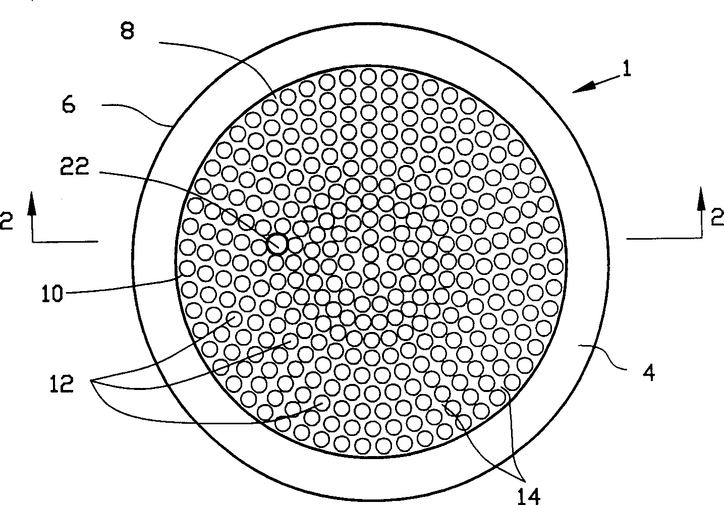
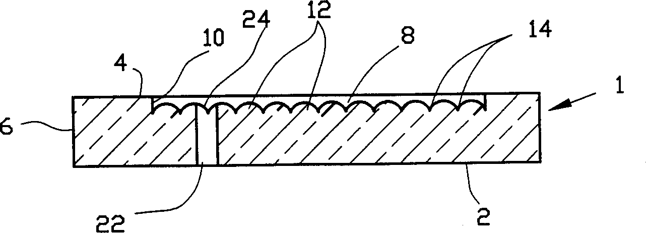
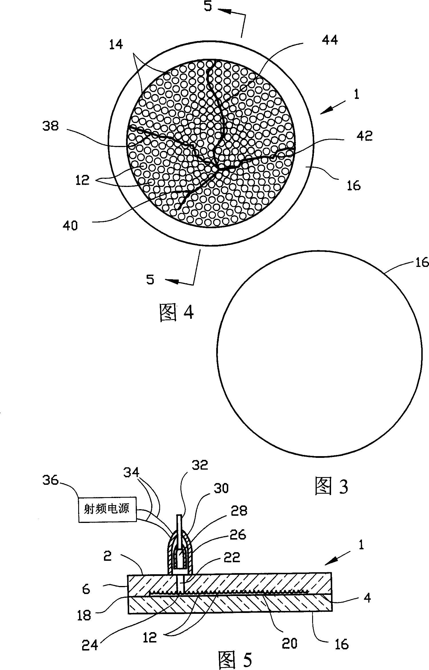
[0026] Such as figure 1 As shown in -5, in the first embodiment of the present invention, the rear glass 1 is preferably molded into a circular body with a suitable mold (not shown), for example, about 300 mm in diameter, and has a rear surface 2, A front surface 4 and an outer peripheral surface 6. A circular recess or cavity 8 is formed in the front surface 4 and has a peripheral radial outer surface 10 extending into the depth or bottom of the cavity. A number of almost semicircular elements or projections 12 extend upwardly from the bottom of the cavity, as figure 2 As shown, the height is lower than that of the peripheral surface 10, the reason for which will be further clarified later in the description. This configuration provides intersticial channels 14 between adjacent elements 12 of the array of elements 12, as figure 1 The array of elements 12 covers the bottom of cavity 8 as shown. Elements 12 may be tapered, conical, or prismatic to provide interstitial chan...


PUM


Abstract

The invention relates to an illuminating display set and its producing method. A front part of transparent glass and a flange area of rear part with flute are fritted. Projecture of rear part is extended from the bottom of flute to front part. Intervals between projectures as well as between the projecture and the front part are very small thus forming a discharging channel. A discharging chamberis formed between the front part and the flute. An open pore is connected to the said chamber through the rear part. A tubular part is installed on the rear part and connected to the open pore that is used to vacuumize, then to fill with ionizable gas. Electrode on the tubular part is used to ionize the gas to generate discharged light. The rear part with flute and the projectures in the invention reduces number of parts.

Description

technical field [0001] The invention relates to a light-emitting display device and a manufacturing method thereof. More particularly, the present invention relates to gas plasma display devices. Background technique [0002] It is well known that light is produced when electricity is passed through a gas. This phenomenon has been applied to display luminous symbols such as numbers, characters, graphics and the like, such as neon signs. Common gases used for this purpose are neon, argon, mercury vapor, or mixtures thereof. [0003] U.S. Patent No. 5,383,295 shows a fairly common flat-panel display device in which three glass or plastic plates are fused together to form a sandwich structure, the outer plates are continuous planes, and the center main part of the central plate is hollowed out. A small chamber is formed to store the desired inert gas. A number of frits or beads fill the inner chamber and act as a sort of separator, providing uniform spacing between the plat...

Claims


Application Information

Patent Timeline
IPC IPC(8): G09F13/26G09G3/28H01J1/62H01J9/24H01J17/02H01J17/16H01J63/04
CPCF21Y2105/00H01J9/241H01J17/16
Inventor 傅庆鸿
Owner JIAYING INT
Features
  • R&D
  • Intellectual Property
  • Life Sciences
  • Materials
  • Tech Scout
  • Unparalleled Data Quality
  • Higher Quality Content
  • 60% Fewer Hallucinations
Learn More