Removable latch and bezel EMI grounding feature for fiber-optic transceivers

a technology of fiber-optic transceivers and latches, which is applied in the direction of optical elements, coupling device connections, instruments, etc., can solve the problems of inadvertent bumping or jarring of the latch member at its distal end, damage to the latch or guide rail, or damage to the integrity of the soldered electrical connection between the guide rail

Inactive Publication Date: 2002-11-26
LUMENTUM OPERATIONS LLC
View PDF23 Cites 107 Cited by
  • Summary
  • Abstract
  • Description
  • Claims
  • Application Information

AI Technical Summary

Problems solved by technology

Because the guide rail of the above-described connector system protrudes through the opening in the bezel, the latch member at its distal end is subject to being inadvertently bumped or jarred.
If the force o

Method used


Image

  • Removable latch and bezel EMI grounding feature for fiber-optic transceivers
  • Removable latch and bezel EMI grounding feature for fiber-optic transceivers
  • Removable latch and bezel EMI grounding feature for fiber-optic transceivers

Examples


Embodiment Construction

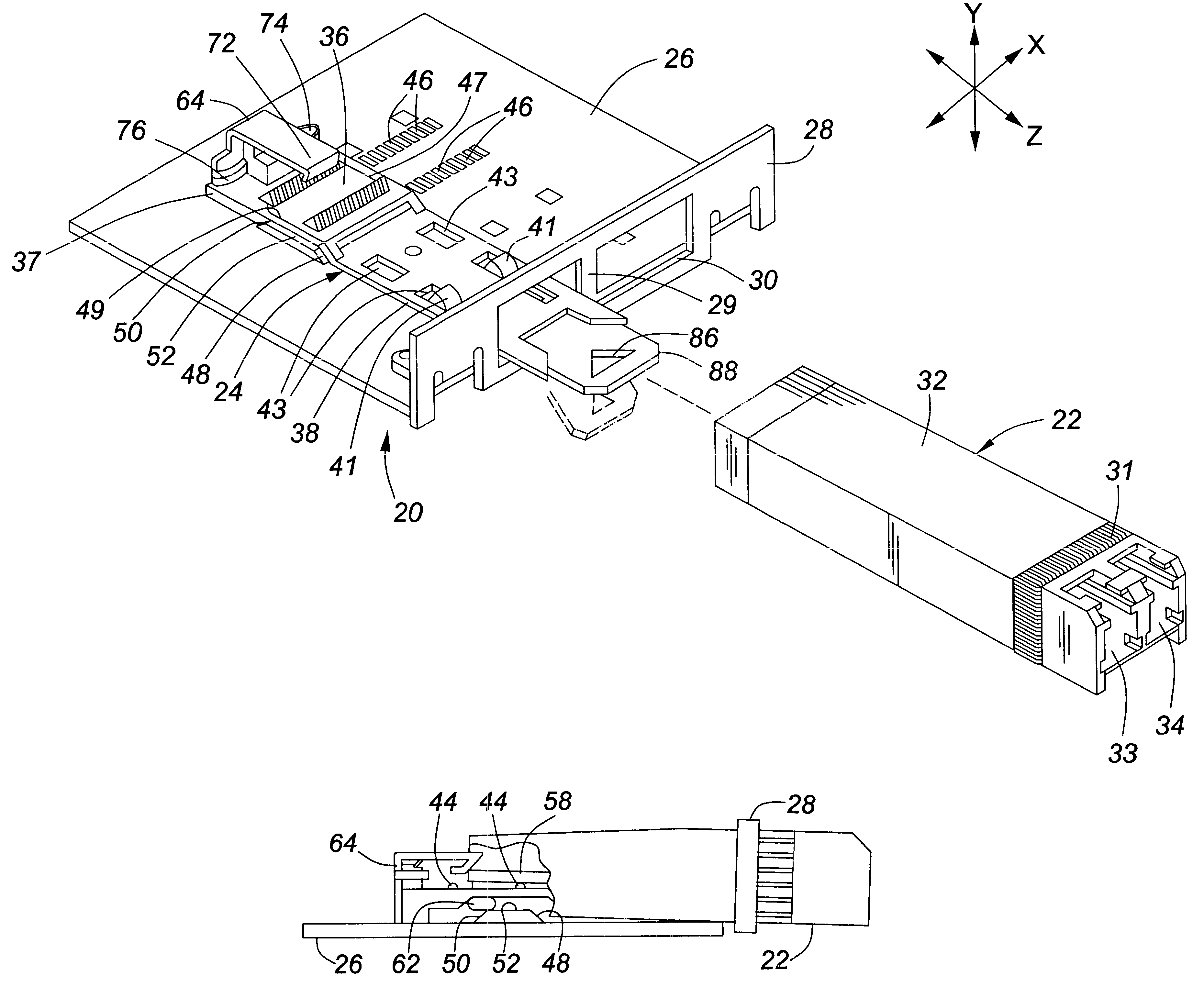
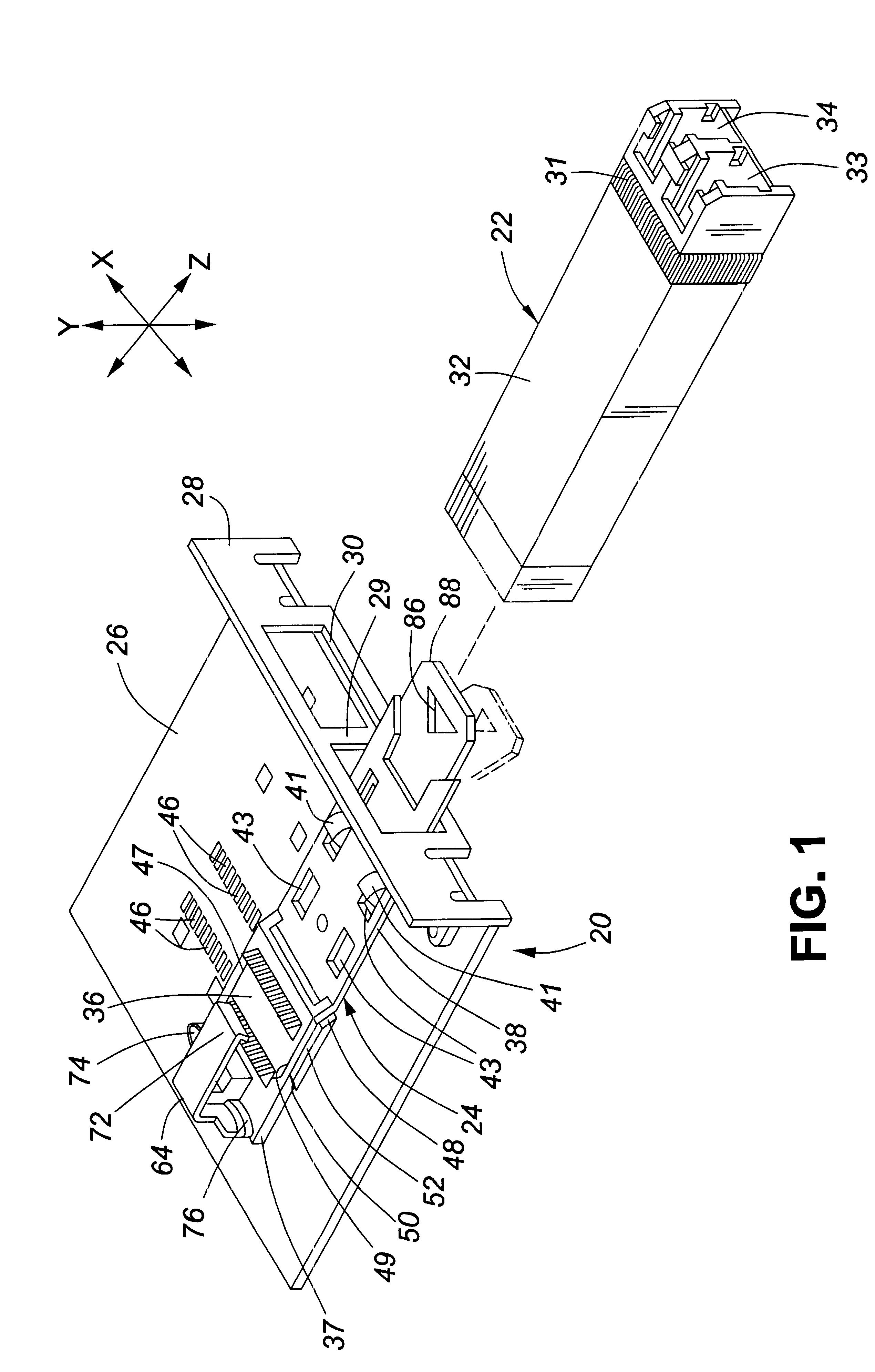
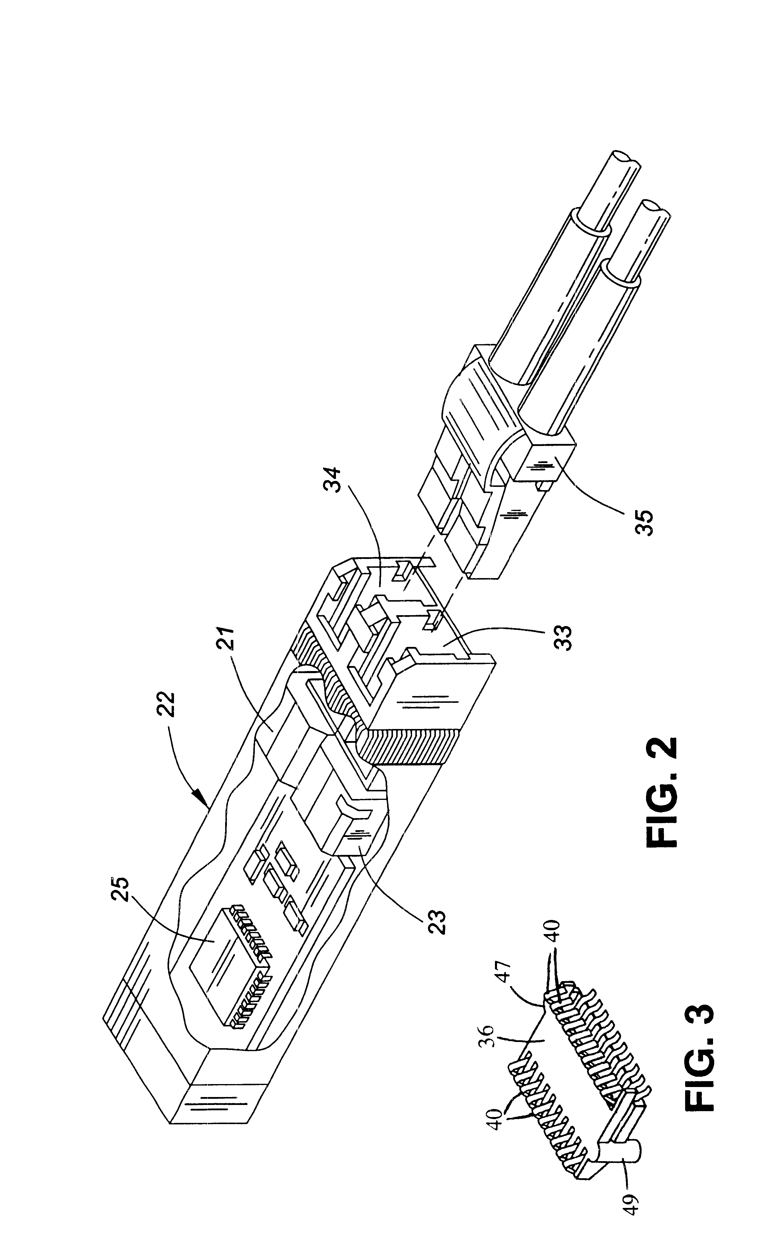
As illustrated in FIG. 1, a peripheral device port assembly 20 of a personal computer or similar device (not shown) is electrically and mechanically mateable with a data transceiver module 22. Transceiver module 22 is preferably a SFF version of the GBIC or SOC type and, as illustrated in FIG. 2, includes suitable optical transceiver electronics, such as a laser photodiode-based transmitter 21, a photodetector-based receiver 23, and suitable integrated circuit chips 25 that contain laser driver preamplifiers and other circuitry of the type conventionally included in optoelectronic transceivers. Module 22 receives and transmits serial optical data and serial electrical data, although parallel optical and / or parallel electrical transmission and reception is also contemplated within the realm of this invention. Module 22 communicates electrical signals to and from peripheral device port assembly 20 using the electrical connector system described below.

Assembly 20 includes a camming ele...


PUM


Abstract

An electrical connector system has two connectors, one of which is included in a module mateable with the other connector in a pluggable manner. The other connector includes an elongated guide rail and a connector block in which are retained two or more electrical contacts. The guide rail by use of snap projections and recesses (11) may extend through an opening in a computer enclosure. A latch member is attached to the end of the guide rail in a manner that releases the latch member from the guide rail if the latch member is bumped or jarred to minimize the likelihood of damaging it. A grounding strip embedded in the guide rail makes electrical contact with the bezel through which it extends to protect against EMI. The ground strip includes raised contact portions (41) that engage a conductive bottom cover (39) of the module (72) and lower contact portions (53) for surface mount to a system circuit board (26).

Description

1. Field of the InventionThe present invention relates generally to electronic connector systems and, more specifically, to low-profile connector systems for user-removable electronic modules, such as transceiver modules that interface with a computer.2. Description of the Related ArtElectrical connectors are used to interconnect circuit cards and other electronic modules or assemblies in computers and other equipment. Various international and industry standards define the type of connectors used to interface computers to external communication devices such as modems, network interfaces, and other transceivers. A well-known type of transceiver developed by an industry consortium and known as a gigabit interface converter (GBIC) or serial optical converter (SOC) provides an interface between a computer and an Ethernet, Fibre Channel or other data communication environment. In co-pending U.S. patent application Ser. No. 09 / 216,014, a connector system is described that includes an opt...

Claims


Application Information

Patent Timeline
IPC IPC(8): H01R13/627H01R13/658G02B6/42
CPCH01R13/6271H01R13/65802G02B6/4246G02B6/4292Y10S439/939Y10S439/923H01R13/6582H01R13/658
Inventor BRANCH, SCOTT MICHAELGAIO, DAVID PETERHOGAN, WILLIAM K.
Owner LUMENTUM OPERATIONS LLC
Why Eureka
Try Eureka