Accurate power detection circuit for use in power amplifier

A power detection circuit, power amplifier technology, applied in the layout of amplifier protection circuit, amplifier, high frequency amplifier, etc., can solve the problems of large size of directional coupler, poor performance of resistance voltage divider, inaccurate measurement, etc. Compact, easy-to-implement, low-cost effects

Inactive Publication Date: 2002-08-28
卡莱汉系乐有限公司
View PDF0 Cites 3 Cited by
  • Summary
  • Abstract
  • Description
  • Claims
  • Application Information

AI Technical Summary

Problems solved by technology

For example, directional couplers are bulky, have high losses, resistive dividers are poor, and taking current samples as a measure of output power is relatively inaccurate

Method used


Image

  • Accurate power detection circuit for use in power amplifier
  • Accurate power detection circuit for use in power amplifier
  • Accurate power detection circuit for use in power amplifier

Examples


Embodiment Construction

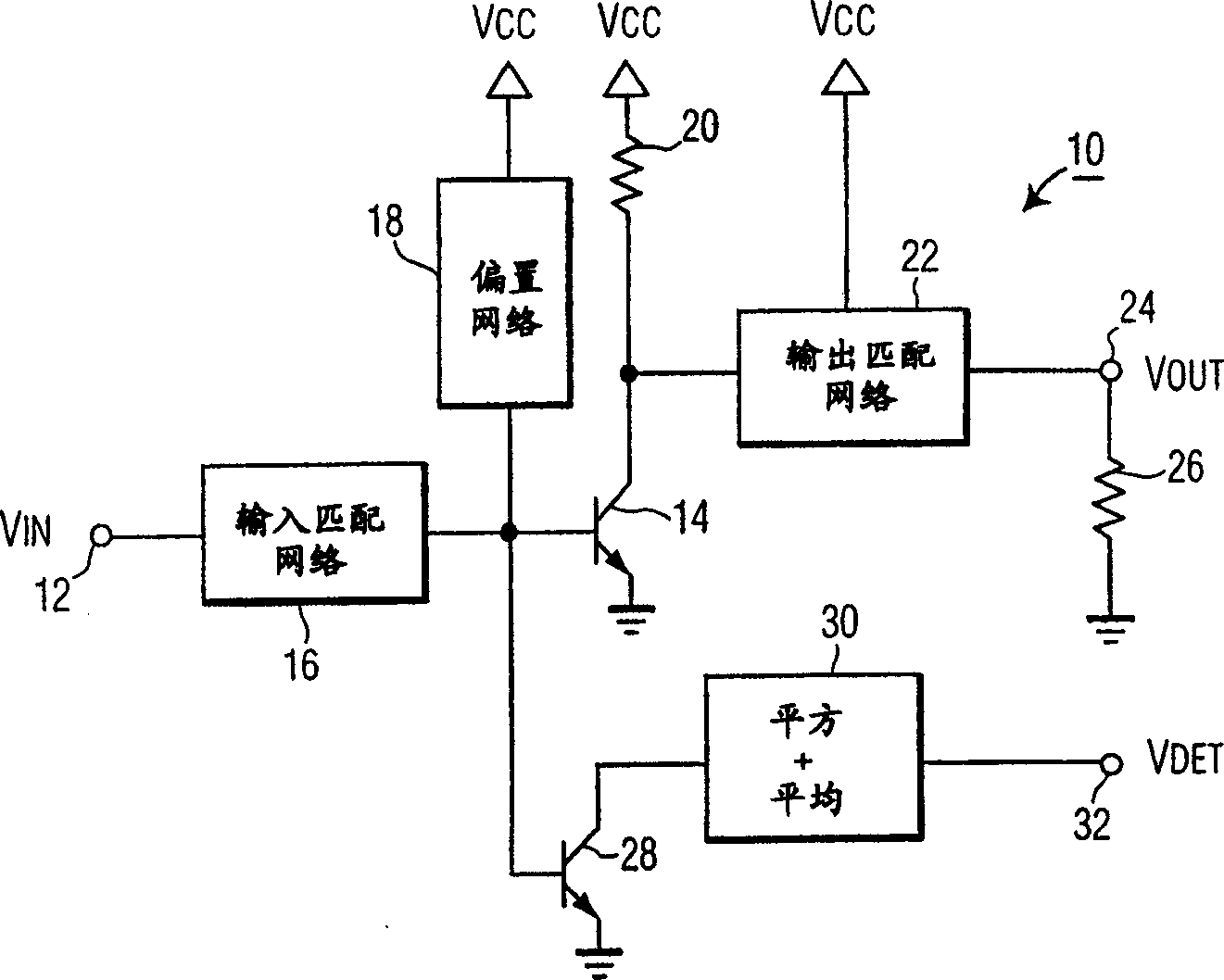
[0019] exist figure 1 A power amplifier circuit 10 for amplifying a signal Vin input from an input terminal 12 is illustrated in a functional block diagram. The amplifier circuit includes an amplifying transistor 14 for amplifying an input signal Vin input from an input terminal 12 to the base of the transistor 14 via an input matching network 16 . It should be noted that the power amplifier circuit can be used in various situations, such as audio amplification, or high frequency amplification such as wireless communication and Internet connection, so the input signal Vin can be an audio signal or a high frequency signal. The power amplifier transistor 14 is biased from the supply voltage through a bias network 18 . It should be understood that circuit parts such as the input matching network 16 and the bias network 18 can be realized by various circuit structures known to those skilled in the art, so no detailed description is given here.

[0020] The output circuit of the ...


PUM


Abstract

A power amplifier circuit for amplifying an input signal includes an amplifying transistor and a power detection circuit. The power detection circuit includes a circuit for generating a signal which is directly proportional to the power level in the amplifying transistor. This may-be accomplished by generating a voltage proportional to the square of a current in the amplifying transistor and then averaging that voltage. In this manner, a more accurate indication of the power level in the amplifying transistor is obtained.

Description

Background of the invention [0001] The present invention relates to transistor amplifier circuits, and in particular to power amplifier circuits and power detection circuits for such power amplifier circuits. [0002] Amplifiers of this type are often used in high frequency amplifiers, such as those used in wireless communication devices, and in audio amplifiers and the like. In such amplifiers, especially when used in high-frequency circuits, it is necessary to display the power level of the output stage. [0003] In the prior art, there are usually no more than two technologies to realize this function. First, a directional coupler or voltage divider can be installed at the output of the power amplifier to sense a portion of the signal presented to the load, and this sampled signal can then be used to display the load power. A second technique used in the prior art is to use a smaller transistor in parallel with the power transistor to generate a sample of the power amplif...

Claims


Application Information

Patent Timeline
Patent Type & Authority Applications(China)
IPC IPC(8): G01R21/06G01R21/10H03F3/19H03F3/213H03F3/343
CPCG01R21/10H03F3/19H03F3/3432H03F3/3435H03F2200/456H03F2200/465H03F2200/75H04B1/04
Inventor T·索拉蒂S·罗
Owner 卡莱汉系乐有限公司
Why Eureka
Try Eureka