

Acoustic device for track
A technology for sound-absorbing devices and rails, which is applied in the direction of rails, noise-absorbing devices, roads, etc., can solve problems such as difficulties, and achieve the effects of increasing maintainability and durability, reducing noise, and high impact resistance
- Summary
- Abstract
- Description
- Claims
- Application Information
AI Technical Summary
Problems solved by technology
Method used
Image

Examples
no. 1 example
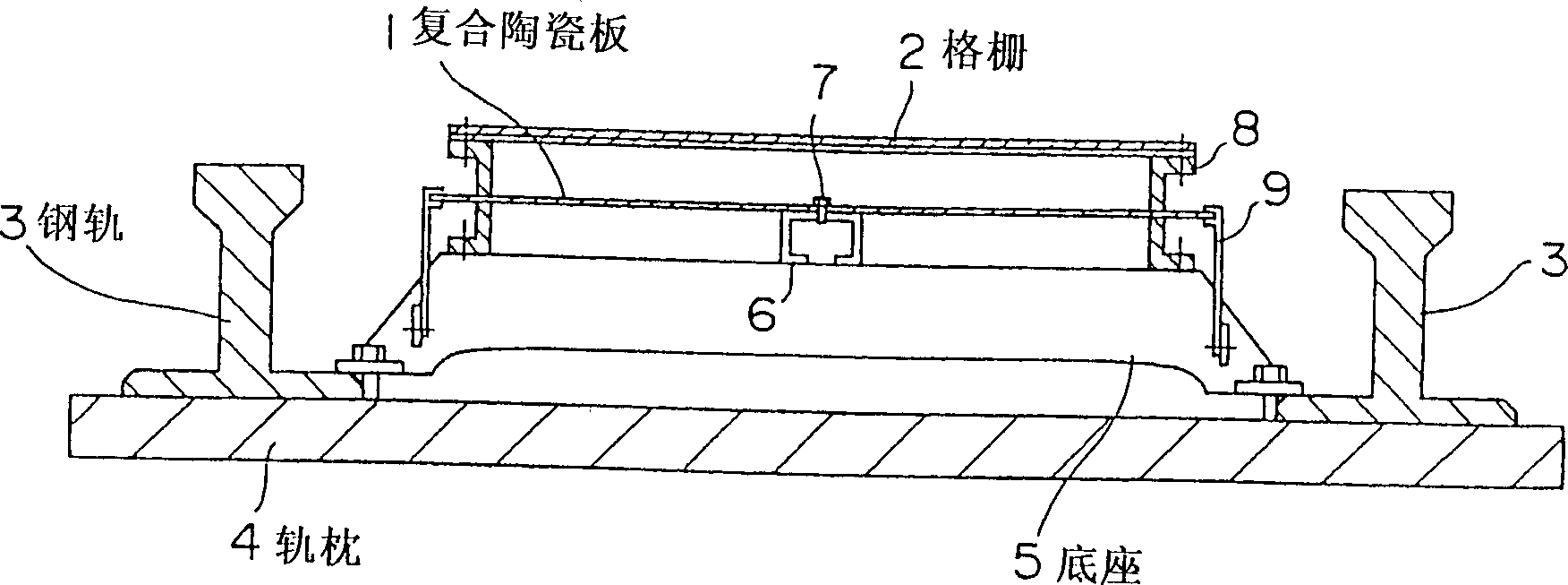
[0023] figure 1 is a side view of a sound absorbing device for rails according to one embodiment. A composite ceramic sound-absorbing panel is used as the sound-absorbing panel in which an aluminum-based ceramic material and an aluminum expanded metal are bonded to each other.
[0024] This embodiment provides a sound-absorbing device, in which a grid 2 is processed, and the thickness of the air layer between the base 5 and the composite ceramic sound-absorbing panel 1 can be controlled. A composite ceramic sound-absorbing panel 1 is installed between the two rails 3 and is supported by a support member 9 and a C-shaped channel steel 6 . The support 9 and the C-shaped channel steel 6 are supported by the base 5 machined below these elements, while the base 5 itself is fixed by different means. For example, the base 5 can be fixed to the sleeper 4 by screwing in nails, or it can also be fixed in the concrete state by anchors in the holes. Of course, it can also be figure 1 ...
no. 2 example
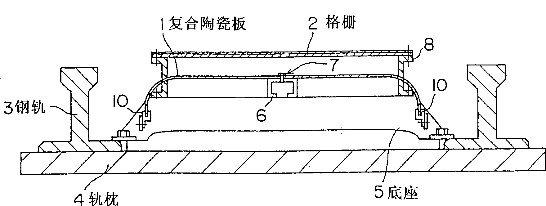
[0030] figure 2 is a sectional view of the sound absorbing device for rails according to the second embodiment. In addition to the structure shown in the first embodiment, this embodiment provides a sound-absorbing device in which both ends of the composite ceramic sound-absorbing panel 1 near the two steel rails 3 are bent at approximately 90 degrees until they are aligned with the The top surfaces of the two rails are perpendicular, thereby forming a curved portion. Since the composite ceramic sound-absorbing panel 1 adopted in the present invention has proper elasticity, it can be bent and used. In this embodiment, by utilizing most of the above-mentioned characteristics of the panel 1 , the composite ceramic sound-absorbing panel 1 is supported by the sound-absorbing panel support 10 , while the middle part of the panel 1 is fixed by the C-shaped channel steel 6 and the bolt 7 .
[0031] The composite ceramic sound-absorbing panel 1 has different sound-absorbing effects...
no. 3 example
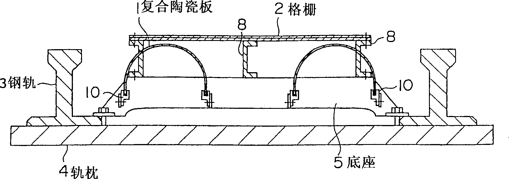
[0033] image 3 is a sectional view of the sound absorbing device for rails according to the third embodiment. In addition to the structure shown in the first embodiment, this embodiment provides a sound absorbing device in which two composite ceramic sound absorbing panels 1 are arranged in parallel so as to be perpendicular to the echo from the bottom of the vehicle. Specifically, in this sound-absorbing device, the two ends of each of the two composite ceramic sound-absorbing panels installed close to each of the two steel rails 3 are bent at approximately 90 degrees until they are aligned with the rails. The top surface is perpendicular to have a curved portion.
[0034] In this embodiment, the two ends of each composite ceramic sound-absorbing panel 1 are fixed by the sound-absorbing panel support 10, and the middle part thereof is not supported. Therefore, each acoustic panel has a bow shape across its entire width. Although in this embodiment two composite ceramic so...
PUM
 Abstract
Description
Claims
Application Information