


Quick Research
Generate reliable direction feasibility study reports for your R&D in just a few steps.

Technical Q&A
Discover and master advanced knowledge NOW. Basics, ideas, possibilities, all at once.

Find Solutions
As an expert in R&D theories, this can generate solutions to your technical problems instantly.

Evaluate Feasibility
Analyze your overall solution with one click, know your potential R&D risks in advance.

Monitor Landscape
Get weekly tech updates, stay abreast of the latest tech innovations and key insights.
Ferrule holding device
A technology of iron hoops and predetermined positions, which is applied in the direction of structural elements, building components, and on-site preparation of building components, which can solve time-consuming and other problems
- Summary
- Abstract
- Description
- Claims
- Application Information
AI Technical Summary
Problems solved by technology
Method used
Image

Examples
Embodiment Construction
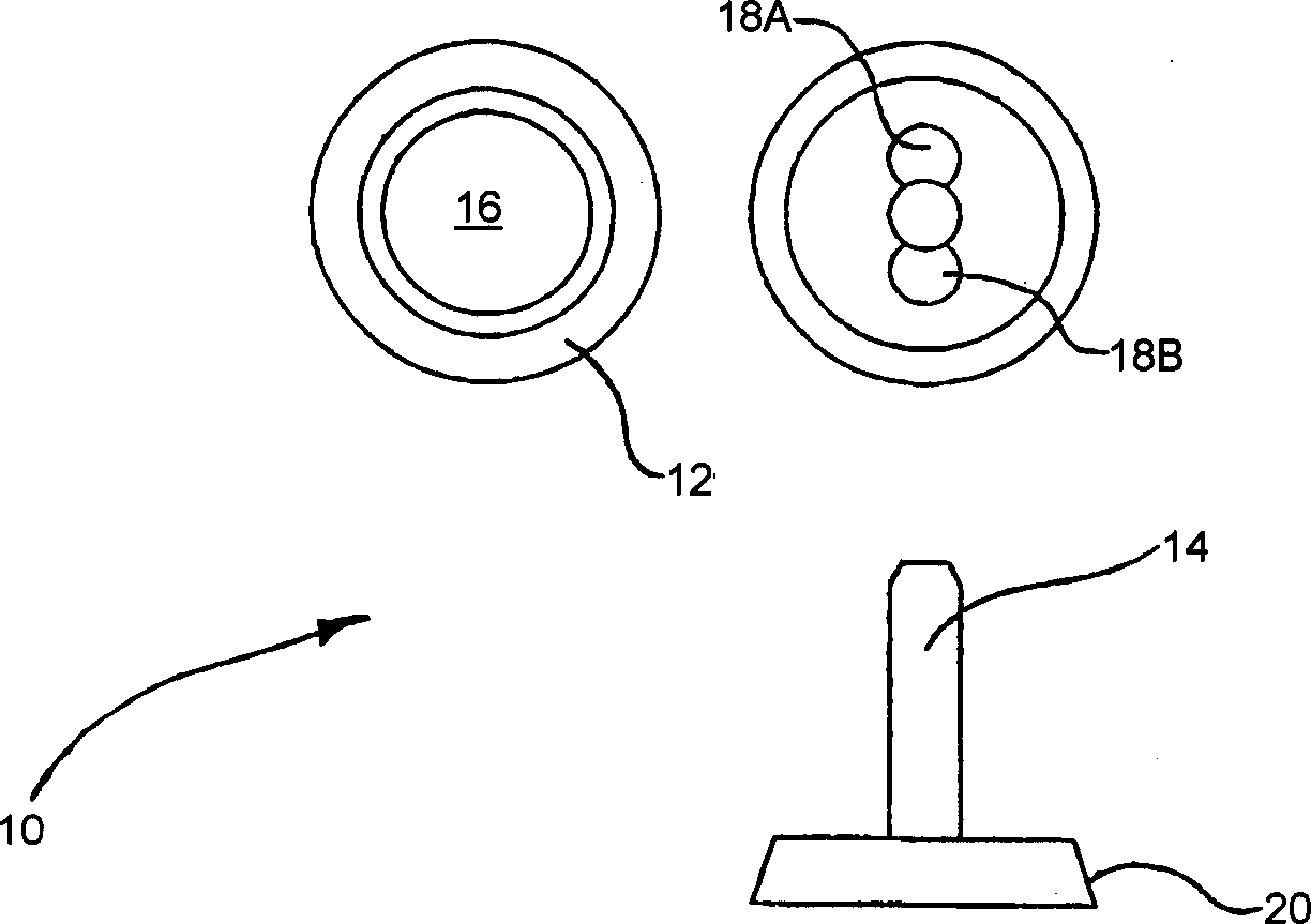
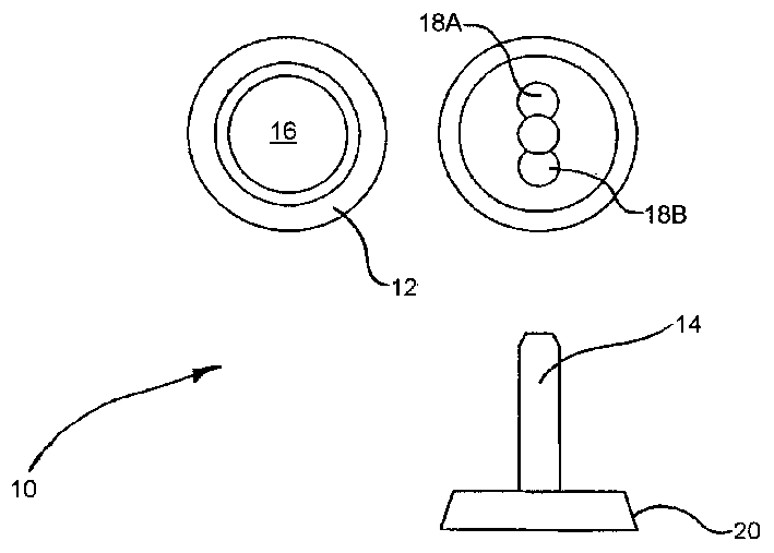
[0022] Such as figure 1 As shown, a ferrule locating tool, generally designated 10 , includes a base 12 and a locating element 14 . The tool 10 of this embodiment includes a magnetic element 16 disposed within the lower surface of the base body 12 and a pair of other magnetic elements 18A and 18B disposed within the upper surface of the base body 12 .
[0023] In this embodiment, the base body 12 is disc-shaped with a tapered peripheral wall 20 . The positioning elements 14 are in the form of pins or dowels which are threaded coaxially with the disc-shaped base 12 via fasteners (not shown). The diameter of the dowel 14 is such that it slidably receives an iron ferrule (not shown). It should be understood, however, that the dowel 14 may be replaced depending on the particular ferrule with which it is to be engaged. The dowel 14 may include a ring or circular magnet (not shown) in the vicinity of its threaded connection to the base 12 . This helps to magnetically secure the ...
PUM
 Abstract
Description
Claims
Application Information
 - R&D Engineer
- R&D Manager
- IP Professional
- Industry Leading Data Capabilities
- Powerful AI technology
- Patent DNA Extraction
Browse by: Latest US Patents, China's latest patents, Technical Efficacy Thesaurus, Application Domain, Technology Topic, Popular Technical Reports.
© 2024 PatSnap. All rights reserved.Legal|Privacy policy|Modern Slavery Act Transparency Statement|Sitemap|About US| Contact US: help@patsnap.com