
Valve, milking claw and milking system

A technology of milking machine and valve body, which is applied in the field of milking claws

Inactive Publication Date: 2002-11-06
DELAVAL HLDG AB
View PDF0 Cites 8 Cited by
  • Summary
  • Abstract
  • Description
  • Claims
  • Application Information

AI Technical Summary

Problems solved by technology

Unfortunately, the valve can inadvertently close when there is a very high milk flow, which is obviously a disadvantage

Method used


Image

  • Valve, milking claw and milking system
  • Valve, milking claw and milking system
  • Valve, milking claw and milking system

Examples


Embodiment Construction

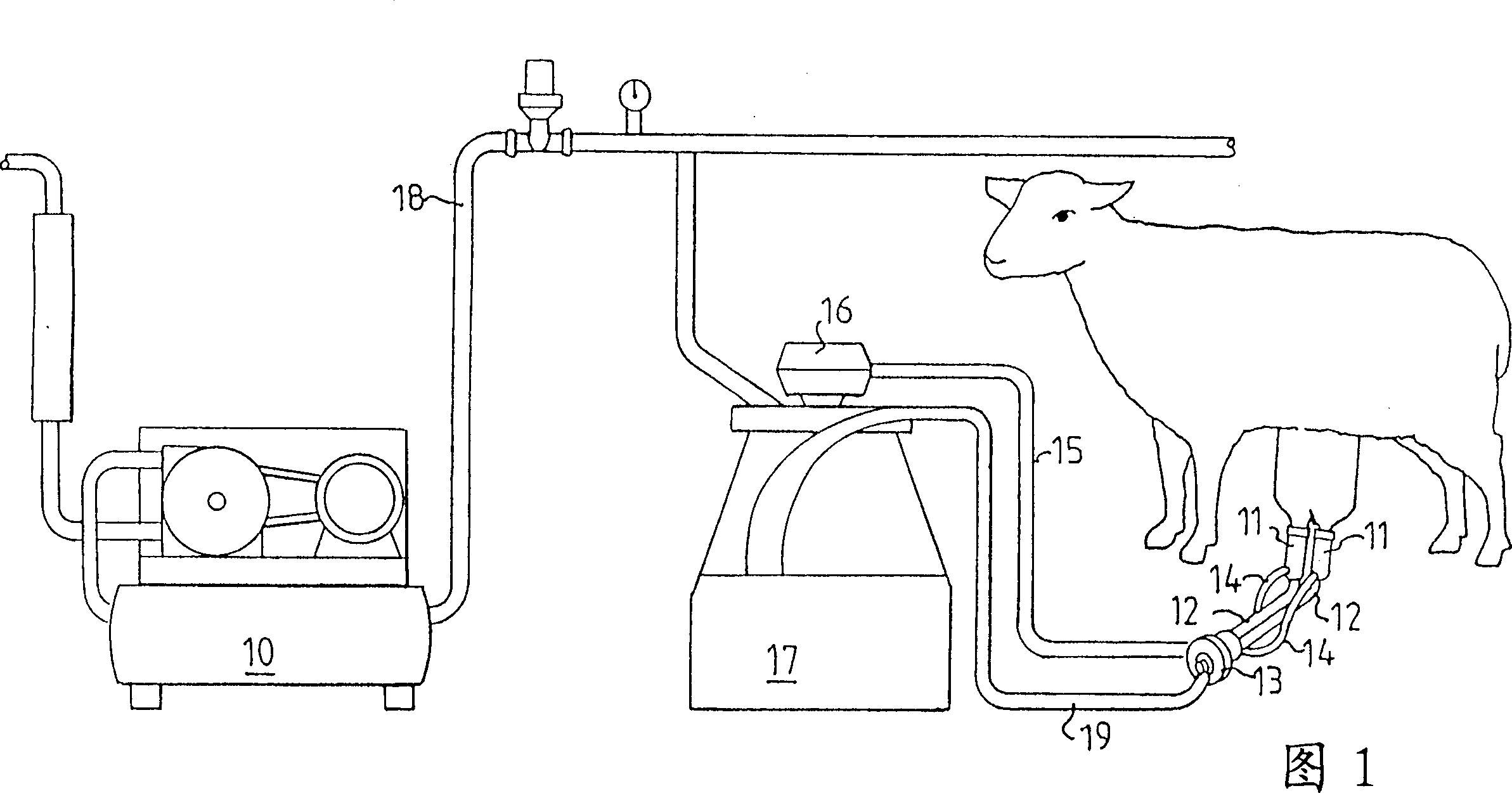
[0016] Figure 1 schematically shows an example of a milking system according to the invention, in this case a system for milking sheep. Only one milking station out of many milking stations driven by a common vacuum pump 10 is shown here. Two milking cups 11 are secured to the teats of the sheep which are milked in a known manner by a pulsating vacuum supplied through short and long pulsating tubes 14 and 15 respectively. A short milk tube 12 leads from the teat cup 11 to a valve according to the invention contained in the jaw 13 from which the milk flows out of the jaw via a long milk tube 19 into a receiving tank 17 .

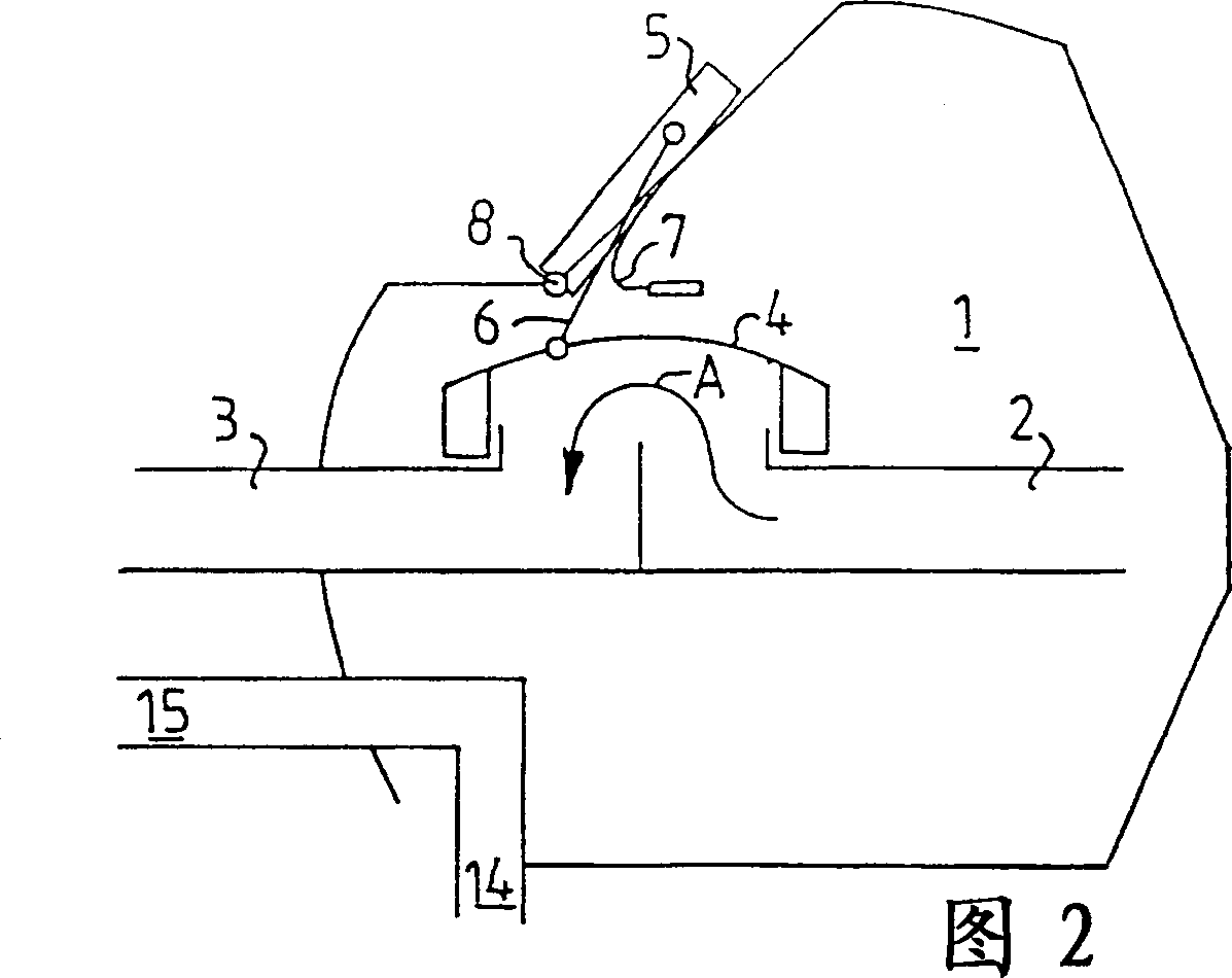
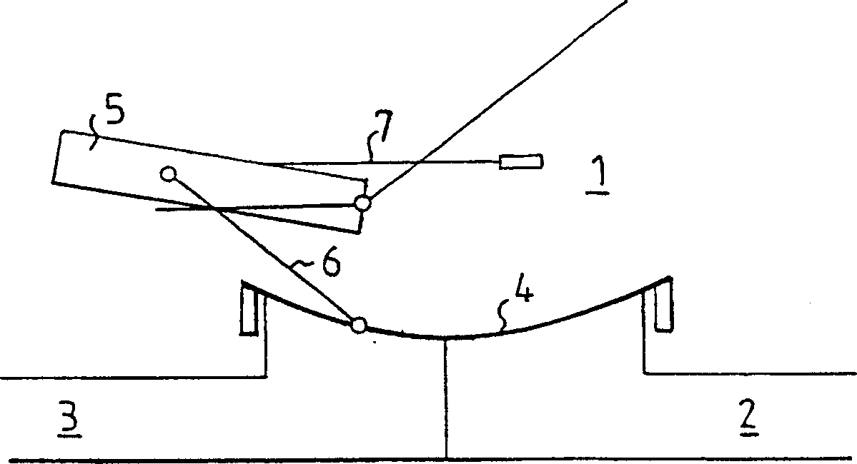
[0017] FIG. 2 shows very schematically a first embodiment of a valve 1 according to the invention which can be accommodated in the jaw 13 shown in FIG. 1 . The inlet 2 of the valve directs milk flow from tube 12 into the valve and, when the valve is in the open position shown in FIG. A diaphragm 4 of elastic material is arranged in its open position shown i...


PUM


Abstract

A diaphragm valve for shutting off the milk flow through the claws of a vacuum-driven milking machine, the valve in a preferred embodiment having a lever (5) connected to the outside of the milk flow with a link (6) on the diaphragm (4), thus avoiding any easily leaking sleeves. The lever (5) can be swung by hand to a position that holds the diaphragm off its seat allowing milk to flow. In the self-closing embodiment, the lever is in this case against the bias of the spring (7) and remains at the position when the suction force acting on the diaphragm (4) and connecting rod (6) is sufficient to overcome the bias of the spring (7). In this open position, this is the case where milk flows normally through the valve. When the milking cup is removed from the animal's teat, only air flows through the valve, thereby reducing the suction force on the linkage (6) and allowing the spring (7) to swing the lever away from its valve-opening position to a loose When the diaphragm is in the open position, air suction will pull the diaphragm, sealing it against the valve seat, cutting off the flow of potentially contaminated air through the system. The principles of the invention can also be implemented on a rotating knob (21) which is attached to the diaphragm (4) and interacts with an inclined groove (23) and a spring (24) biasing the knob to Advance to a position where the diaphragm is released when flow is insufficient. This system is especially useful on sheep or goat dairy farms where milking cup assemblies are frequently installed and removed.

Description

technical field [0001] The present invention generally relates to milking claws containing a novel valve design suitable for use in milking machines and milking systems suitably containing a number of such valves. Background technique [0002] In known milking systems actuated by suction, milking claws have been used which provide a confluence of milk flowing from all milking cup assemblies, in the case of milking equipment for goats or sheep Two milking cups, four milking cups are used in milking equipment for cows. Milk flows from the claws into the milk receiving container. It has been found advantageous to provide a means to shut off the air flow through the valve when the teatcup is removed or dropped from the teat, or before the teatcup is removed from the teat. This can be done manually or automatically. The claw valves generally known for this purpose use an intermediate shaft which is provided with a circular knob on the outside of the valve body for manual o...

Claims


Application Information

Patent Timeline
IPC IPC(8): A01J5/04F16K7/12
CPCA01J5/041A01J5/044A01J5/048F16K7/126
Inventor 耶克·奥贝里托尔比约恩·彼得松
Owner DELAVAL HLDG AB
Learn More