Current sensor

A current detector and current technology, applied in the field of detectors, can solve problems such as failing to meet accuracy requirements

Inactive Publication Date: 2002-11-13
SENTEC SA
View PDF2 Cites 28 Cited by
  • Summary
  • Abstract
  • Description
  • Claims
  • Application Information

AI Technical Summary

Problems solved by technology

However, such current transformers are also sensitive to magnetic field gradients and therefore do not meet sufficient accuracy requirements when used in financial electricity meters

Method used


Image

  • Current sensor
  • Current sensor
  • Current sensor

Examples


Embodiment Construction

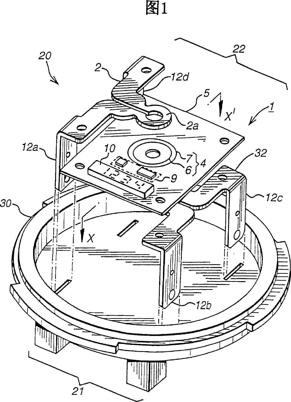
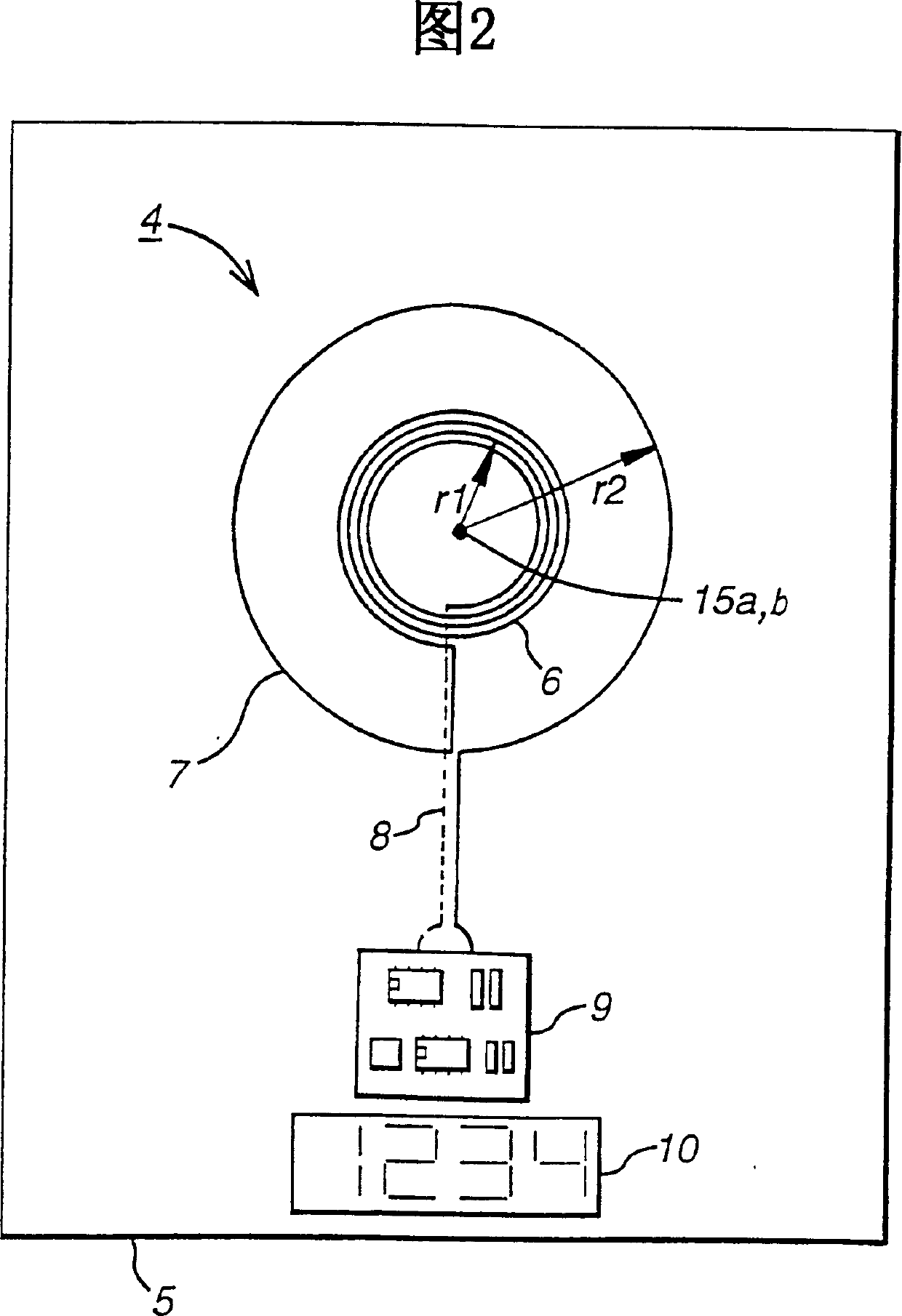
[0025] FIG. 1 shows a partially exploded view of a financial electricity meter 20 , which includes an electricity meter base 30 , a power line input 21 , a power line output 22 and a current detector 1 . The current detector 1 includes a first load conductor 2 and a second load conductor 32 connected between the power line input 21 and the power line output 22 , and through which a main current flows. The power line input 21 is connectable to a "2S" 3-wire, 240 Volt (120V) Root Mean Square (RMS) 60 Hertz (60Hz) single phase center tapped mains (commonly used in US residential premises) , a current with an RMS value of 0A to 200A can flow from the power supply mains. The power line output 22 is connectable to a residential premises. The current detector 1 also includes a sensor printed circuit board 5 on which a current sensing coil 4 including a sensing part 6 and an offset compensation part 7 is formed. In this embodiment, the sensing portion 6 is annular and is located coa...


PUM


Abstract

The invention discloses a fiscal electricity meter for measuring energy supplied to a load. The load current flows through the primary coil of a sensor and induces an EMF (Electromotive Force) that can represent the current flowing in the secondary coil. The secondary coil includes a sensing winding arranged to couple more strongly to the primary coil and a canceling compensation winding having the same and opposite multi-turn conductor areas so as to provide an inactive response to an external magnetic field. The windings are arranged so that their magnetic axes are coaxial and aligned so that they also provide ineffective response to external magnetic fields with field gradients.

Description

technical field [0001] The invention relates to a detector which can be used to measure the current flowing in a conductor. More particularly, but not exclusively, the present invention relates to a current detector forming part of an alternating current (AC) fiscal electricity meter used to meter energy supplied by a utility company to commercial or residential premises. Background technique [0002] Several different methods are known for measuring current. One of these methods is to use a resistor in a circuit to establish a voltage across the resistor that is proportional to the current flowing through the resistor. However, this approach suffers from ohmic heating of the shunt resistors and lack of galvanic isolation between the measured current and the established voltage. [0003] Other current measurement methods detect and measure the magnetic field caused by the current flowing through the conductor. These methods generally have the advantage of providing electr...

Claims


Application Information

Patent Timeline
Patent Type & Authority Applications(China)
IPC IPC(8): G01R15/18
CPCG01R15/18G01R15/185
Inventor 安德鲁·尼古拉斯·达姆爱德华·格雷利耶·科尔比
Owner SENTEC SA
Why Eureka
Try Eureka