Valve assembly of reciprocating compressor

A compressor and valve assembly technology, which is applied to engine components, variable displacement pump components, liquid variable displacement machinery, etc., can solve the problem of increased noise, reduced compression efficiency of compressors, and fracture of reed valve 61 and stopper 71 and other problems to achieve the effect of preventing leakage and improving compression efficiency

Inactive Publication Date: 2002-12-11
SAMSUNG GWANGJU ELECTRONICS CO LTD
View PDF0 Cites 7 Cited by
  • Summary
  • Abstract
  • Description
  • Claims
  • Application Information

AI Technical Summary

Problems solved by technology

Even in this case, since the position of the stopper 71 limited by the positioning member 73 and the resistance exerted by the stopper 61 do not change, the pressure in the inner chamber 23a of the cylinder is limited because the degree of opening of the discharge hole 31b is limited. Increase
Due to the increased pressure

Method used


Image

  • Valve assembly of reciprocating compressor
  • Valve assembly of reciprocating compressor
  • Valve assembly of reciprocating compressor

Examples


Embodiment Construction

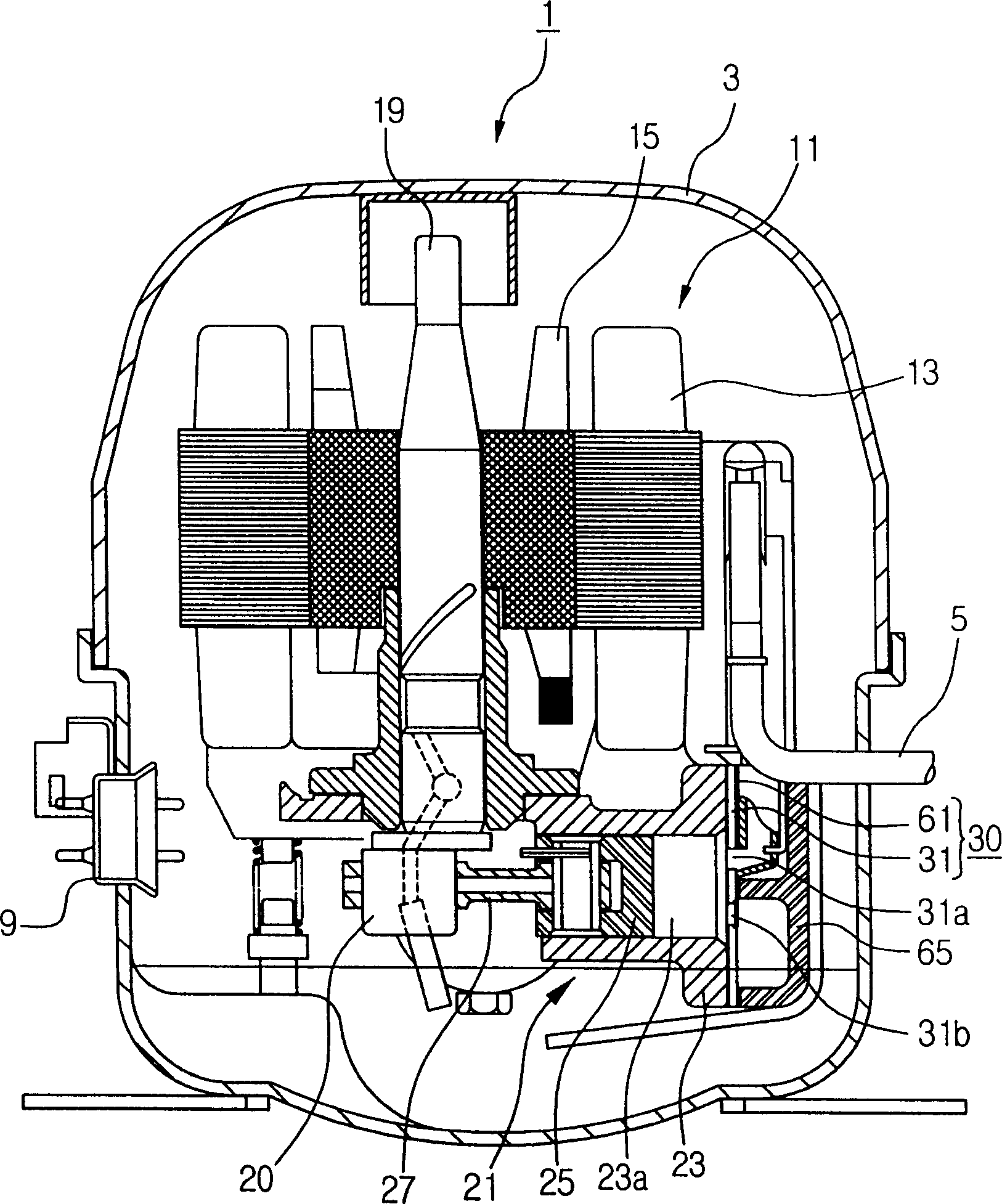
[0023] Preferred embodiments of the present invention will be described below with reference to the accompanying drawings. Throughout this specification, for figure 1 Components that are the same as those of the conventional compressor will be given the same reference numerals, and descriptions thereof will be omitted.

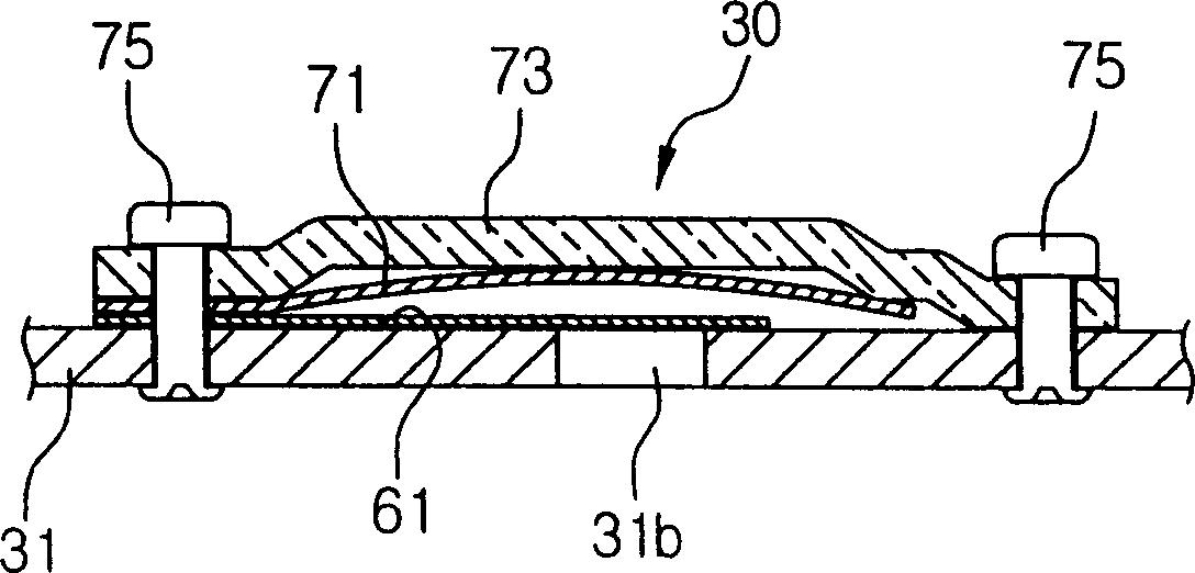
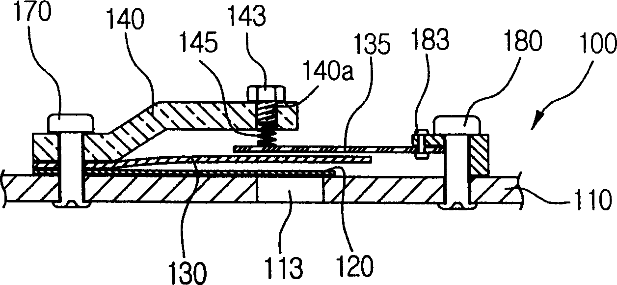
[0024] image 3 is an enlarged cross-sectional view of a valve assembly according to the present invention. The valve assembly 100 according to the present invention includes: a valve plate 110 with a suction hole (not shown) and a discharge hole 113; a positioning member 140 fixed on the valve plate 110 by a fastening bolt 170; The reed valve 120 between the pieces 140; and the first and second stoppers 130 and 135 for resisting the deformation force of the reed valve 120.

[0025] The reed valve 120 opens and closes the discharge hole 113 . During the movement of the piston 25 from the top dead center to the bottom dead center, the cylinder device 21 suc...


PUM


Abstract

A valve assembly of a hermetic reciprocating compressor. It includes a valve plate provided between a cylinder block and a cylinder head, a reed valve for opening/closing a refrigerant discharge hole formed on the valve plate, and a first stopper for resisting bending deformation of the reed valve. Force, the second stopper, used to resist the bending deformation force of the first stopper, and the positioning piece used to limit the bending degree of the second stopper, and cooperate with the positioning piece to be used for being bent by the reed valve Bolts to which the stoppers are attached. When the refrigerant discharge pressure increases, the resistance against the bending force is applied alternately by the first stopper and the second stopper, thereby increasing the compression efficiency by changing the opening degree of the reed valve corresponding to the pressure change, and at the same time Noise can be reduced by dampening the vibrations applied to the reed valve. When the discharge pressure of the refrigerant increases abnormally, the degree of deformation of the second stopper restricted by the positioning member is controlled by the bolt.

Description

technical field [0001] The present invention relates to a valve assembly of a reciprocating compressor, which is installed on a cylinder head of the compressor for controlling discharge operation of refrigerant compressed in the cylinder. Background technique [0002] Freezing systems such as refrigerators have compressors for compressing refrigerant. figure 1 The hermetic reciprocating compressor shown is an example of a compressor. [0003] The compressor 1 has a housing 3 having a sealed inner space defined therein, a cylinder device 21 for compressing refrigerant, and a driving motor for driving the cylinder device 21 . [0004] A suction pipe 5 for sucking gaseous refrigerant, a discharge pipe (not shown) for discharging refrigerant compressed by the compressor 1 , and an electrical contact 9 for supplying power to the compressor 1 are formed inside the casing 3 . [0005] The drive motor 11 has a stator 13 , a rotor 15 and a shaft 19 rotated by the stator 15 . The s...

Claims


Application Information

Patent Timeline
IPC IPC(8): F04B39/10F16K15/16F16K17/04
CPCF04B39/1073F16K15/16Y10T137/7892F16K15/161F16K15/162F04B39/10
Inventor 洪明重
Owner SAMSUNG GWANGJU ELECTRONICS CO LTD
Why Eureka
Try Eureka