Multi-carrier communication device and peak power suppressing method
A multi-carrier communication and multi-carrier signal technology, applied in multi-carrier systems, multiplexed communications, modulated carrier systems, etc., can solve problems such as increased unwanted radiation, degraded transmission characteristics, and degraded error rates
- Summary
- Abstract
- Description
- Claims
- Application Information
AI Technical Summary
Problems solved by technology
Method used
Image
Examples
Embodiment 1
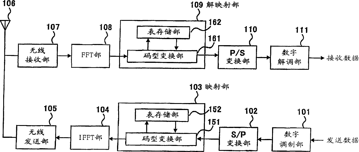
[0057] Fig. 2 is a structural block diagram of a multi-carrier communication device according to Embodiment 1 of the present invention.
[0058] The multi-carrier communication device in Embodiment 1 of the present invention mainly includes a digital modulation unit 101, an S / P conversion unit 102, a mapping unit 103, an IFFT unit 104, a wireless transmission unit 105, an antenna 106, a wireless reception unit 107, an FFT unit 108, a solution Mapping unit 109 , P / S conversion unit 110 , and digital demodulation unit 111 .
[0059]The mapping unit 103 includes a code conversion unit 151 and a table storage unit 152 . The demapping unit 109 includes a code conversion unit 161 and a table storage unit 162 .
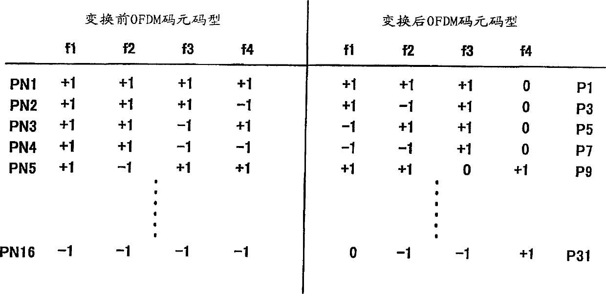
[0060] In FIG. 2 , a digital modulation unit 101 digitally modulates transmission data, and outputs the modulated serial data to a serial-to-parallel (S / P) conversion unit 102 . The S / P conversion unit 102 performs serial-to-parallel conversion on the serial data, assigns ...
Embodiment 2
[0101] FIG. 8 is a structural block diagram of a multi-carrier communication device according to Embodiment 2 of the present invention. However, the same reference numerals are assigned to the same structures as in the first embodiment, and detailed description thereof will be omitted.
[0102] In the present embodiment, the following situation is described: the demapping section includes a code pattern collation section 251 for checking the symbol code pattern, a table storage section 252 storing a symbol code pattern correspondence table, and a request is made when the symbol code pattern does not correspond. The retransmission request unit 253 for retransmission and the code conversion unit 254 for performing symbol code conversion request retransmission when there is an error in the symbol data.
[0103] Hereinafter, the operation of the multicarrier communication device according to the second embodiment will be described with reference to FIG. 8 .
[0104] The wireless ...
Embodiment 3
[0115] In this embodiment, a case will be described in which error correction is performed when there is no error in receiving OFDM.
[0116] FIG. 9 is a structural block diagram of a multi-carrier communication device according to Embodiment 3 of the present invention. However, the same reference numerals are assigned to the same structures as in the first embodiment, and detailed description thereof will be omitted.
[0117] In the structure shown in FIG. 9, the demapping part 301 includes a code pattern collation part 351 for comparing a symbol code pattern with reference to a correspondence table, a table storage part 352 for storing a symbol code pattern correspondence table, and a device for correcting an error symbol code pattern. An error correction unit 353, and a code conversion unit 354 that converts the symbol code according to the correspondence table.
[0118] The code pattern collation section 351 checks whether the received OFDM symbol is the symbol code patte...
PUM
 Abstract
Description
Claims
Application Information
 - R&D
- Intellectual Property
- Life Sciences
- Materials
- Tech Scout
- Unparalleled Data Quality
- Higher Quality Content
- 60% Fewer Hallucinations
Browse by: Latest US Patents, China's latest patents, Technical Efficacy Thesaurus, Application Domain, Technology Topic, Popular Technical Reports.
© 2025 PatSnap. All rights reserved.Legal|Privacy policy|Modern Slavery Act Transparency Statement|Sitemap|About US| Contact US: help@patsnap.com


