Sinker device of flat knitting machine

A technology of sinkers and flat knitting machines, applied in textiles and papermaking, weft knitting, knitting, etc.

Inactive Publication Date: 2003-01-15
SHIMA SEIKI MFG LTD
View PDF1 Cites 12 Cited by
  • Summary
  • Abstract
  • Description
  • Claims
  • Application Information

AI Technical Summary

Problems solved by technology

[0004] However, in the case of this sinker device, in order to perform the above-mentioned required actions on the sinker, it is necessary to separately set up a control system for the advance and retreat operation of the sinker and a control system for the advance and retreat operation of the sinker stop holding plate.

Method used


Image

  • Sinker device of flat knitting machine
  • Sinker device of flat knitting machine
  • Sinker device of flat knitting machine

Examples


Embodiment Construction

[0024] The best embodiment of the sinker device of the present invention will be described in detail below together with the accompanying drawings.

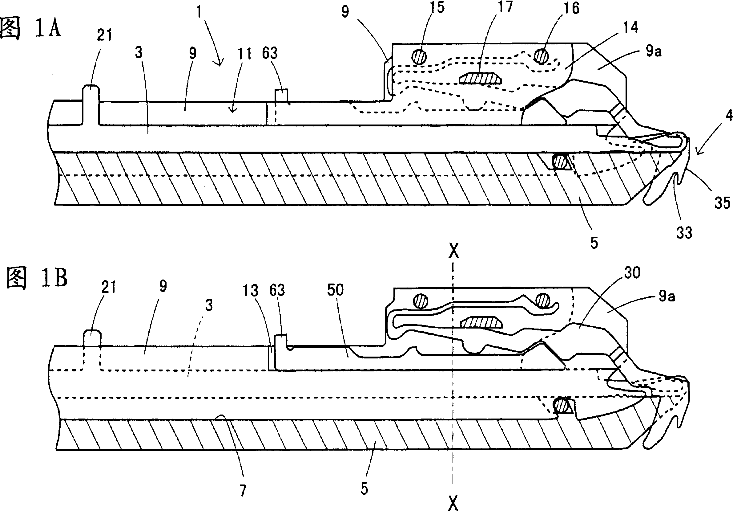
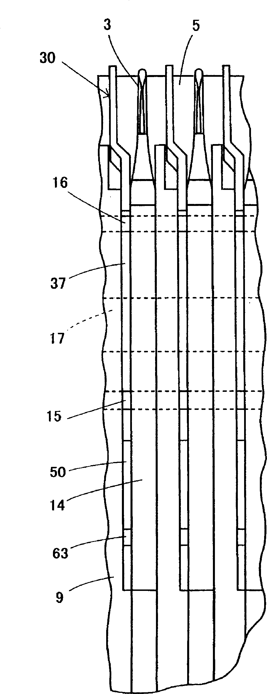
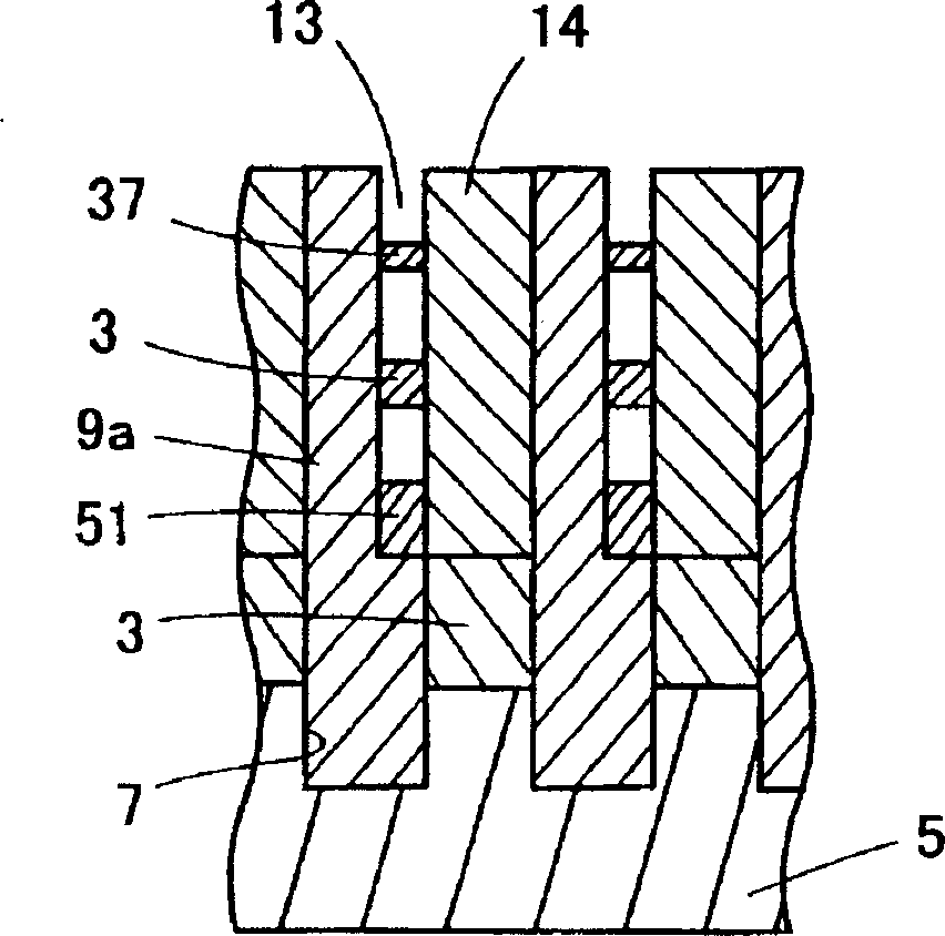
[0025] In the sinker device of the present embodiment, the cross mechanism is as follows: the needle beds 1 provided with many knitting needles 3 are arranged oppositely in front and back with the teeth gap 4 sandwiched, and any one or both needle beds can slide along its length direction. Figure 1 shows only one side of the needle bed, where the latch needles are installed. In the needle bed 1 , a needle plate 9 is erected among a plurality of hooks 7 engraved on a base plate 5 . Knitting needles 3 are accommodated in needle grooves 11 between these needle plates 9 and 9 . The front part 9a on the needle mouth side of the needle plate 9 is formed to be one step higher than the other parts, and the sinker pusher 50 and the upper sinker 30 are accommodated in the housing part 13 formed by cutting off one side of this part. On th...


PUM


Abstract

A sinker device, comprising a sinker jack (50) movable forward and backward relative to a tooth port and a sinker (30) supported swingably on the upper surface of the sinker jack, wherein the sinker (30) and sinker jack (50) form slidably contact surfaces slidingly contacting with each other on the front side of a swinging pivot and, when the sinker jack (50) advances toward the tooth port (4) and moves relative to the sinker (30), the swinging posture of the sinker (30) is swingably controlled to such a height that the sinker (30) presses at least a knitted loop, releases the knitted loop, and performs a knit formation by the relation of slidable contact between the slidable contact surfaces.

Description

technical field [0001] The invention relates to a sinker device of a flat knitting machine which is energized in the direction of pushing down a coil ring between needle beds arranged opposite to each other. Background technique [0002] The present applicant previously proposed the sinker device shown in Japanese Patent Application Laid-Open No. Hei 9-31806. In this sinker device, the pivot branch portion of the sinker is supported in the semicircle-shaped pivot branch groove provided on the needle plate. In the state of being energized by the elastic energizing device to push down the coil ring direction of the coil joint hook of the sinker at ordinary times, the sinker can be freely rotated forward and backward with the pivot branch of the sinker as the rotation axis. There is a control butt on the sinker, and by combining the cam provided on the carriage to overcome the energizing force of the aforementioned energizing device, the sinker retreats from the tooth gap to c...

Claims


Application Information

Patent Timeline
Patent Type & Authority Applications(China)
IPC IPC(8): D04B15/06D04B15/36D04B35/02
CPCD04B15/06D04B15/362D04B15/68D04B15/70D04B15/10
Inventor 森田敏明
Owner SHIMA SEIKI MFG LTD
Why Eureka
Try Eureka