Switch over improving method between power source and frequency converter

A frequency converter, variable technology, applied in the direction of electrical components, transportation and packaging, AC motor control, etc., to achieve the effect of smooth transition and convenience

Inactive Publication Date: 2003-01-22
OTIS ELEVATOR CO
View PDF1 Cites 12 Cited by
  • Summary
  • Abstract
  • Description
  • Claims
  • Application Information

AI Technical Summary

Problems solved by technology

However, although the drive motor alternates between being powered by the AC line and the frequency converter, high transient currents may still be generated; more precisely, this is due to the line frequency and the output frequency of the Frequency drift between the drive motor and its phase shift angle when switching between its frequency converter feed is also due to the induction of the drive motor which can lead to overloading the frequency converter and abrupt changes in the movement of the conveyor system voltage's sake

Method used


Image

  • Switch over improving method between power source and frequency converter
  • Switch over improving method between power source and frequency converter
  • Switch over improving method between power source and frequency converter

Examples


Embodiment Construction

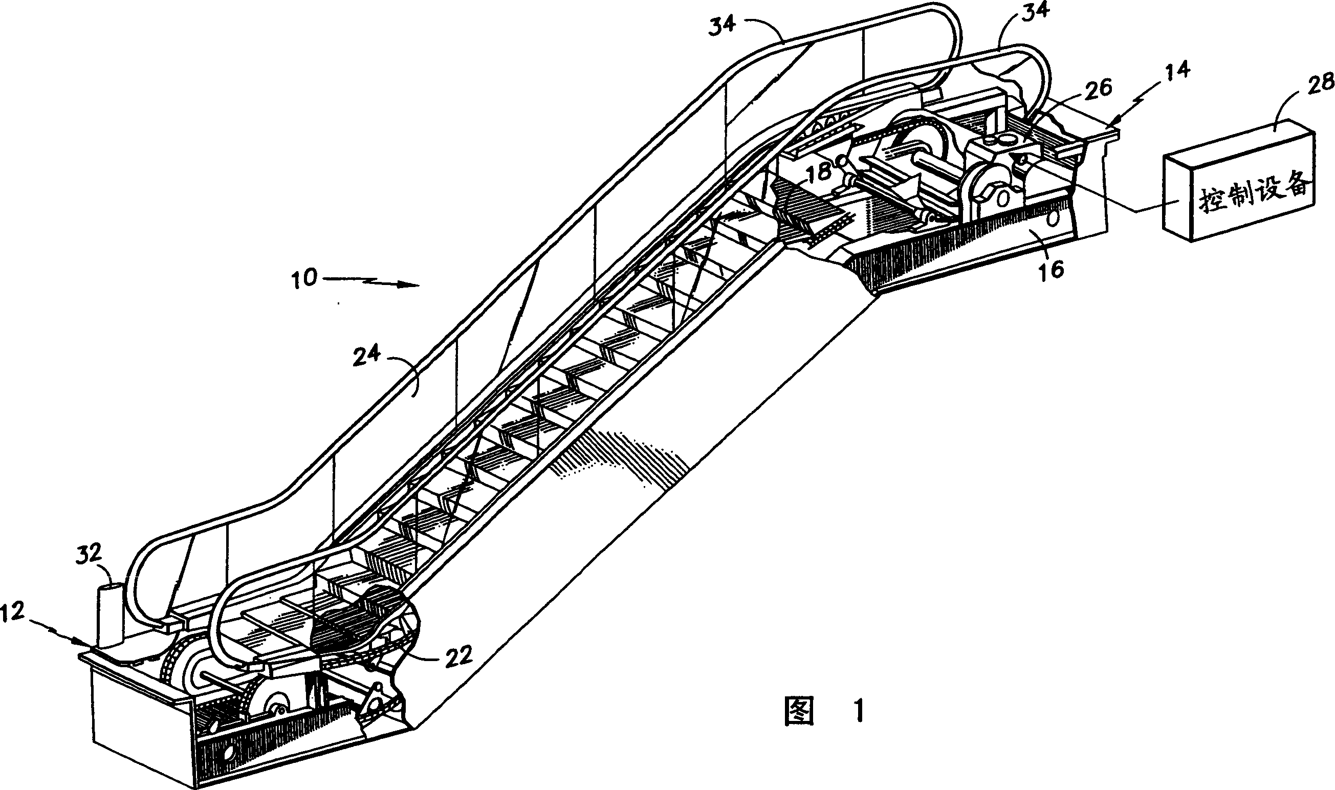
[0030] An escalator, shown in partial section and in perspective view in Figure 1, will be described as an example of a conveyor system according to the present invention.

[0031] As shown in Figure 1, the escalator 10 comprises a landing 12, an upper landing 14, a support frame 16, many step plates 18 which are connected successively to form a continuous band, a dragging device for driving the step plates 18. Dynamic chain 22, a pair of railings 24 extending on both sides of the connected step plate 18, a driving motor 26 coupled with the drag zipper 22 in the form of a driving device, a control that acts simultaneously with the driving motor 26 Device 28, and a device 32 for signaling the need to deliver in the form of a passenger sensor, which may be, for example, an on / off photocell control device but may also consist of a step mat, or a hand switch, or a foot switch . The step plate 18 forms a platform for conveying passengers between the two landings 12 and 14 . Each ...


PUM


Abstract

Process and device for controlling the drive means of a conveyor system 10, specifically in the form of an escalator or passenger conveyor, which can be switched from load to no-load operation, comprising a drive motor 26 and a variable frequency converter 42, which at is least controllable with respect to the frequency of its output voltage, wherein, under load, the drive motor 26 is supplied with a line voltage with an essentially constant line frequency and, at no-load, is supplied the output voltage of the variable frequency converter's 42, wherein, prior to a changeover from no-load to load operation, the output frequency of the variable frequency converter 42 is essentially brought with phase accuracy to the line frequency by means of a PLL device 30, and wherein this changeover is brought about as soon as this phase conformance has been realized.

Description

technical field [0001] The invention relates to a method and a device for controlling a drive mechanism of a conveyor system in the form of an escalator or a passenger conveyor, switchable between loaded and unloaded operation. The conveyor system comprises AC line voltage terminals, an electric drive motor, more precisely in the form of an induction motor or a synchronous motor, and a frequency converter. Background technique [0002] A typical conveyor system for carrying passengers, in the form of an escalator or passenger conveyor, consists of a number of closely adjoining flow plates in the form of a continuous belt moved by means of drive motors. [0003] In order to reduce the power consumption and wear of these types of conveyor systems, methods have been developed whereby the movement of the conveyors of such conveyor systems is activated only when conveying is required, and vice versa. then stop the system. For this purpose, there is provided a device for signali...

Claims


Application Information

Patent Timeline
Patent Type & Authority Applications(China)
IPC IPC(8): B66B25/00H02P27/16
CPCB66B25/00Y02B50/225Y02B50/00
Inventor S·斯潘哈克H·霍尔布吕格尔R·亨克尔
Owner OTIS ELEVATOR CO
Why Eureka
Try Eureka